
Holographic Projection System with Optical Wave Tracking and with Means for Correcting the Holographic Reconstruction

a projection system and optical wave tracking technology, applied in the field of holographic projection systems, can solve the problems of undisturbed propagation of modulated light waves prior to undisturbed propagation, and achieve the effect of reducing the effects of aberration of optical elements

Active Publication Date: 2010-04-29
SEEREAL TECHNOLOGIES
View PDF29 Cites 73 Cited by
  • Summary
  • Abstract
  • Description
  • Claims
  • Application Information

AI Technical Summary

Benefits of technology

[0032]Considering the above-mentioned problems of the prior art in dynamically adapting the compensation of optical errors in a large tracking range during optical wave tracking, it is the object of this invention to reduce the effects of aberrations of the optical elements, in particular of the display screen, such that the entire three-dimensional scene can be seen in the visibility region with as little errors as possible for each eye position of an observer in a large tracking range. In addition, all object light points of the 3D scene shall be reconstructed free of any aberrations if possible.
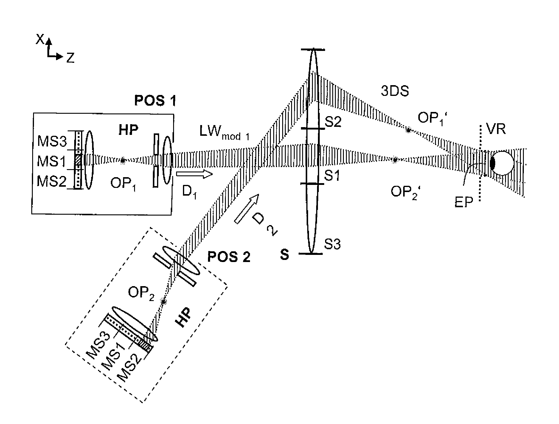
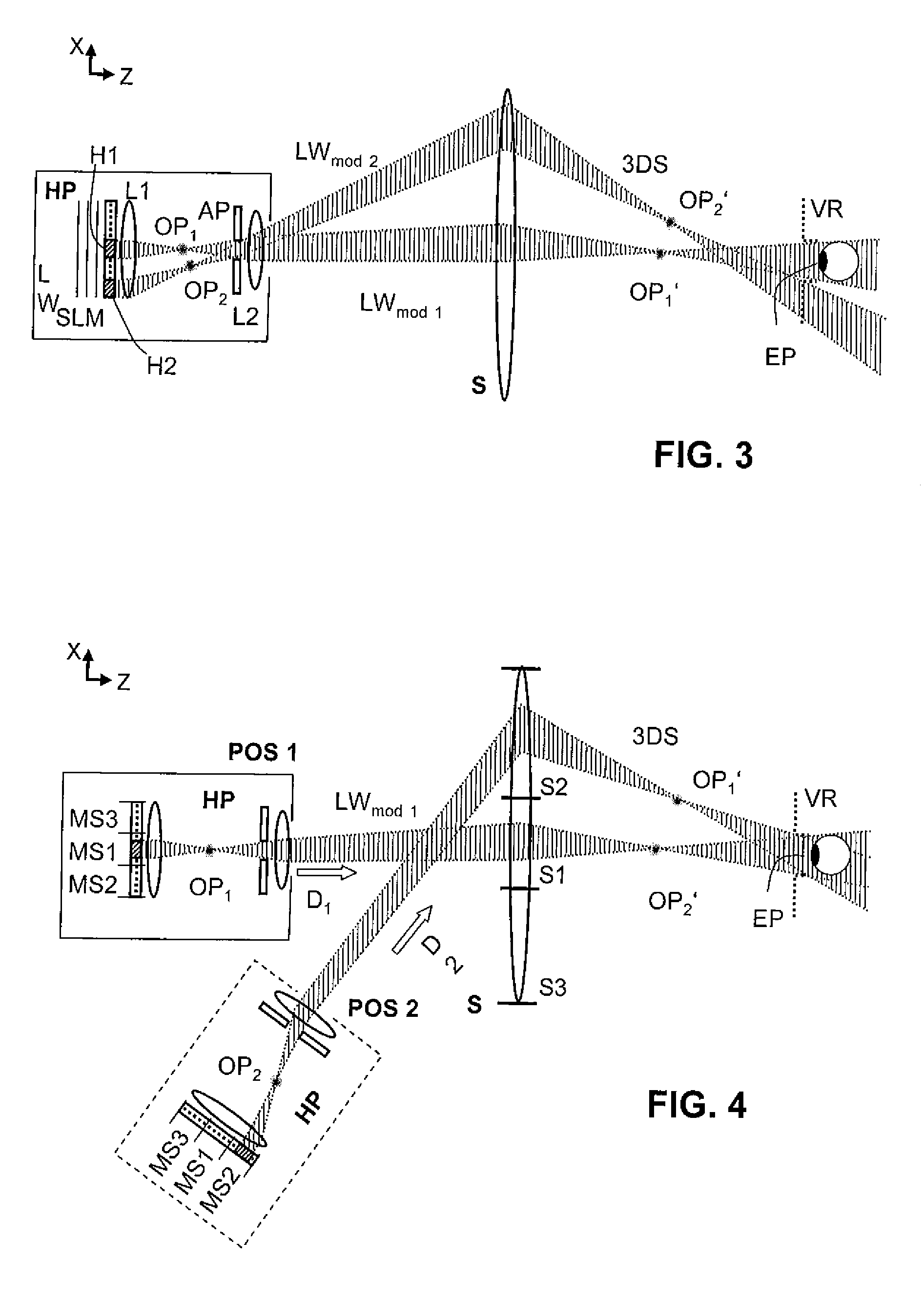
[0041]A reconstruction of the scene using the means according to the present invention has the advantage that the system controller can adjust the wave propagation, through the direction of propagation and the exit positions, for each modulated partial wave to the position of the corresponding screen segment on the display screen and to the desired eye position in the tracking range. Depending on the desired eye position and the corresponding screen segment, the system controller adjusts for each modulated partial wave an angle of incidence on the display screen, so that the reconstructed segments of the scene of all partial waves appear with little aberration and completely on the desired eye position in the visibility region.
[0043]In another embodiment of the invention, the projection system comprises multiple holographic projectors, which are distributed locally and which are controlled in a space multiplex process. Each projector is associated with one screen segment of a single display screen, and generates a discrete partial wave for that screen segment with a direction of propagation that corresponds to that screen segment. This has the advantage that, while the current video hologram is replayed, the exit position of the holographic projectors does not have to be moved in order to achieve an adjustment to another screen segment. It will only be moved in order to track the corresponding partial waves if the eye position changes. These movements can be performed at a significantly lower speed than the adjustment of exit position and direction of propagation to different screen segments during the period of a video hologram within a sequence of moving video holograms.
[0046]Therefore, a preferred embodiment of the present invention comprises an adjustable optical wave tracking means which sequentially adjust the exit position and direction of propagation of the modulated partial waves to different screen segments within a video hologram using optical wave deflecting means. The optical wave deflecting means change the exit position and direction of propagation of the partial waves without any change of the physical position of the holographic projector. This has the advantage that the projector does not have to be moved at least for the sequential adjustment of the projection positions and direction of propagation to different screen segments. Such optical wave tracking means deflect the modulated partial waves for example with the help of a mirror system with partially moving mirrors.

Problems solved by technology

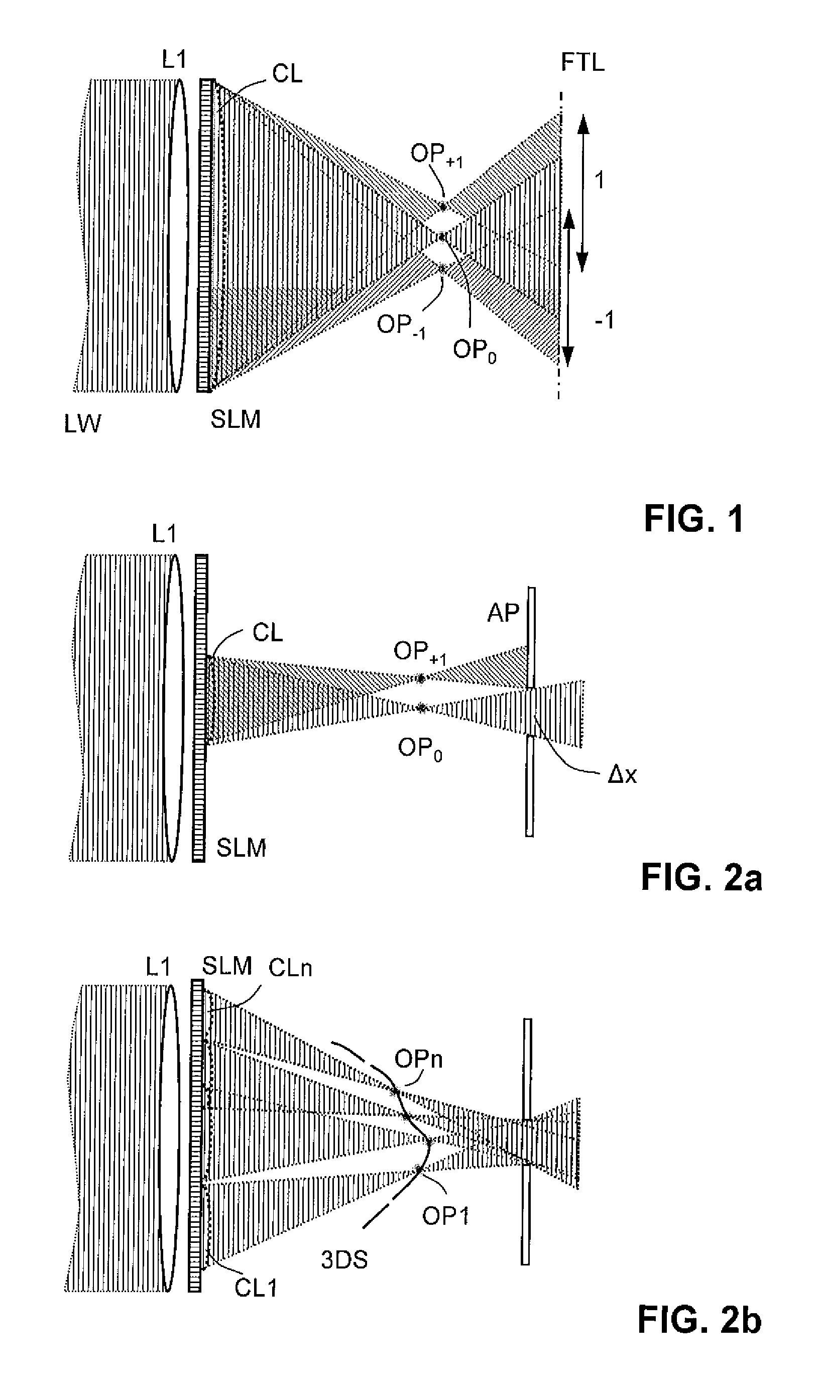
However, it is disadvantageous that a large holographic representation requires for large diffraction angles a much higher resolution of the light modulator means than would be necessary for a two-dimensional representation, as is described by the known sampling theorem.
Another known problem in a reconstruction system is an undisturbed propagation of the modulated light waves prior to generating interference.

Method used


Image

  • Holographic Projection System with Optical Wave Tracking and with Means for Correcting the Holographic Reconstruction
  • Holographic Projection System with Optical Wave Tracking and with Means for Correcting the Holographic Reconstruction
  • Holographic Projection System with Optical Wave Tracking and with Means for Correcting the Holographic Reconstruction

Examples


Embodiment Construction

[0058]FIG. 3 describes the basic principle of a holographic projection system which is used for the embodiment of this invention. The problem which is solved by the invention will be described again in this context. The holographic projection system comprises mainly a holographic projector HP and a focussing display screen S, which shall be very large in order to have a wide viewing angle, and which shall either be transmissive, i.e. a lens, or reflective, i.e. a concave mirror, and it also comprises a computer-aided system controller (not shown).

[0059]The holographic projector HP comprises a modulator illumination means which illuminates the modulator surface of a spatial light modulator SLM with a plane wave LW which is capable of generating interference. The light modulator SLM has an areal arrangement of modulator cells, which are dynamically encoded by a hologram processor (not shown) with holographic information of a desired three-dimensional scene. Like in conventional hologr...


PUM


Abstract

A holographic projection system with a display screen and an optical wave tracking means for controlling the direction of propagation of a modulated wave uses a position controller and an eye finder. An extremely wide tracking range is realised in the projection system for simultaneous viewing of the reconstruction by multiple observers, which are situated beside one another. The reconstruction of the scene is reconstructed for each eye position of an observer such that the entire scene is visible in the visibility region in a large tracking range with minimal errors. The projection system reconstructs the scene with the help of modulated partial waves. Projection means direct these partial waves with separately holographically reconstructed segments of the scene at the desired eye position through a structure of screen segments which are at least horizontally staggered on the display screen.

Description

FIELD OF APPLICATION OF THE INVENTION[0001]The present invention relates to a holographic projection system which, if an observer changes his position while watching a holographic reconstruction of a three-dimensional scene, tracks the propagation direction of a modulated light wave, which carries the holographic reconstruction, to the eye positions of a least one observer with the help of means for optical wave tracking, namely a position controller and an eye finder. The invention relates in particular to means for reducing the effect of optical deformations to the modulated light wave, which are caused by that wave tracking.[0002]The invention is independent of the way the holographic information is provided, and it can be used in systems which allow multiple observers to watch holographically reconstructed video scenes simultaneously.TECHNICAL BACKGROUND OF THE INVENTION[0003]A holographic reconstruction system in the sense of this invention preferably reconstructs moving three-...

Claims


Application Information

Patent Timeline
Patent Type & Authority Applications(United States)
IPC IPC(8): G03H1/08H04N13/00
CPCG03H1/08G03H1/2205G03H1/2294G03H2001/221G03H2210/30G03H2001/2242G03H2001/2292G03H2226/05G03H1/2249G03H2001/2239
Inventor SCHWERDTNER, ARMINOLAYA, JEAN-CHRISTOPHEFLON, STANILAS
Owner SEEREAL TECHNOLOGIES
Learn More