Distance measuring device

a technology of optical distance measuring and measuring apparatus, which is applied in the direction of distance measurement, instruments, surveying and navigation, etc., can solve the problems of increasing the size and complexity of the distance measuring apparatus, reducing the imaging quality of one-sided coatings and sometimes even two-sided coatings, and occupying less installation space. , the effect of improving robustness

Pending Publication Date: 2021-09-30
LEICA GEOSYSTEMS AG
View PDF11 Cites 0 Cited by
  • Summary
  • Abstract
  • Description
  • Claims
  • Application Information

AI Technical Summary

Benefits of technology

[0033]The thin and light weight solution requires considerable less installation space than optical elements according to prior art such as a sealing layer with a hole, beam shaper and a black glass and above that provides improved robustness. In particular, the reduced weight is advantageous for measuring devices with a rotating optical element resp. fast rotating axis such as laser scanners.

Problems solved by technology

Laser light scattered at side faces or edges of the glass part or in the glass part can cause measuring artefacts, for example due to short cuts from the optical transmitter channel to the optical reception channel.
All one-sided coatings and sometimes even two-sided coatings diminish imaging quality, since the substrate is distorted.
This optical compensating element increases the size and the complexity of the distance measuring apparatus.

Method used


Image

  • Distance measuring device
  • Distance measuring device
  • Distance measuring device

Examples


Embodiment Construction

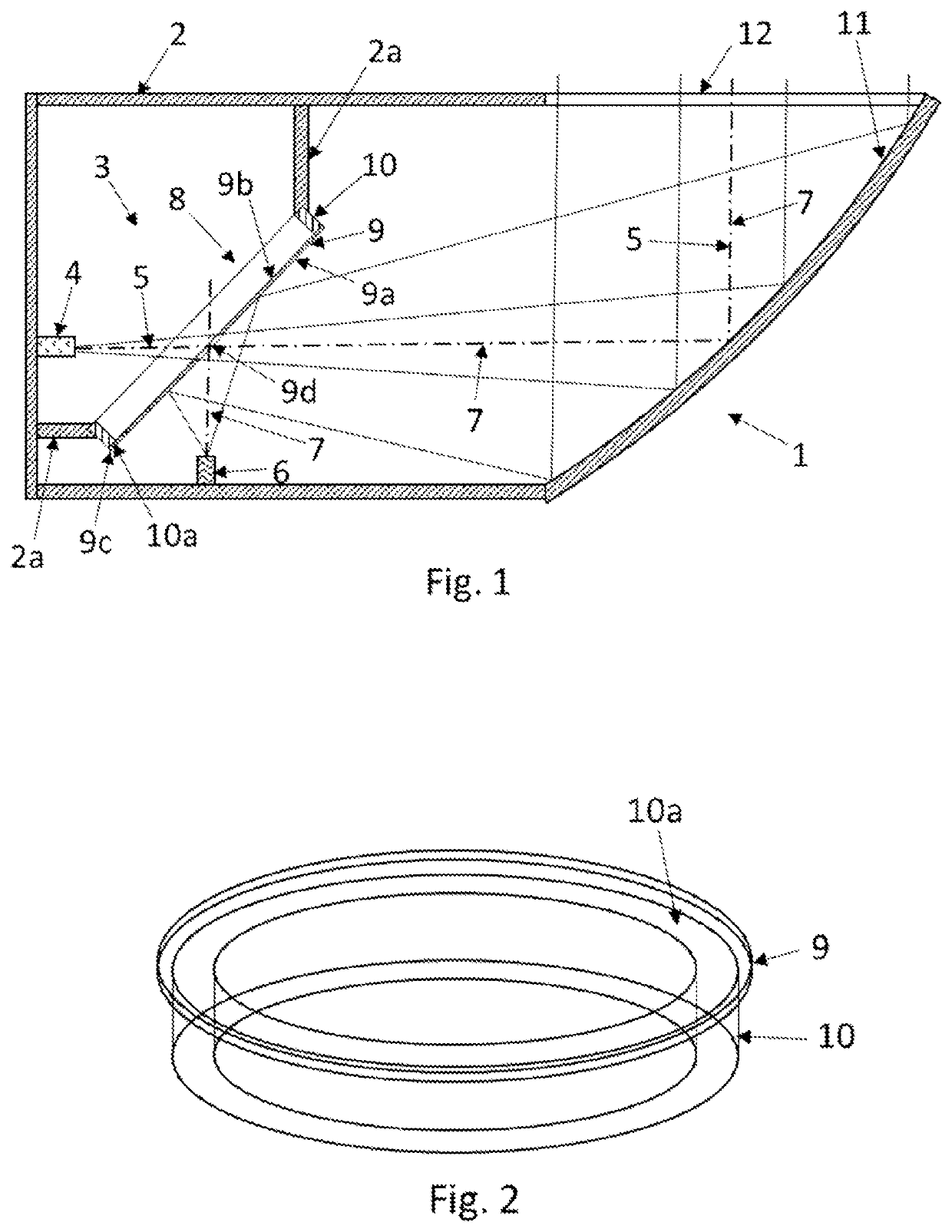
[0041]FIG. 1 shows a distance measuring device 1 with a housing 2. A distance measuring module 3 is arranged in the housing 2 and comprises an optical transmitter 4 for transmitting laser light along a transmitter path 5 and an optical receiver 6 for receiving laser light along a reception path 7. An optical element 8 with a glass part and a coated surface is positioned in the optical transmitter channel 5 and in the optical reception channel 7.

[0042]The optical element 8 includes a glass pane 9 with two surfaces 9a, 9b and with a peripheral edge 9c. In the shown embodiment, the surface 9a is coated with a coating which is at least partially reflecting laser light of the optical reception channel 7 and thereby decoupling an end part of the reception channel 7 from a beginning part of the transmitter path 5. The reflection can depend on wave length and / or polarization of the laser light. The laser light of the optical transmitter path 5 is pathing through a central hole 9d in the gla...


PUM

PropertyMeasurementUnit
thicknessaaaaaaaaaa
thicknessaaaaaaaaaa
diameteraaaaaaaaaa

Abstract

A distance measuring device comprising an optical transmitter channel for transmitting laser light along a transmitter path and an optical reception channel for receiving laser light along a reception path. At least one optical element including a glass part with a coated surface is positioned in the optical transmitter channel or in the optical reception channel. The glass part includes a glass pane with a thickness below 0.3 mm, with a peripheral edge and with a coating on at least one of the two surfaces, and a ring element. The glass pane is adhesively connected to an end face of the ring element. This distance measuring device shows reduced measuring artefacts and/or reduced optical aberration effects and/or a reduced weight.

Description

CROSS-REFERENCE TO RELATED APPLICATIONS[0001]This application claims priority to European Patent Application No. 20166083.4, filed on Mar. 26, 2020. The foregoing patent application are incorporated herein by reference.FIELD OF INVENTION[0002]The present invention relates to an optical distance measuring device with at least one optical element for guiding laser light of at least one laser beam.BACKGROUND[0003]Distance measuring devices are built and named according to their fields of application. Examples are geodetic surveying devices such as electronic tachymeters, total stations, multi-stations, or (single beam or multi beam) laser scanners for geodetic or industrial surveying purposes or laser trackers. These devices share the feature that they comprise at least one radiation source for generating a distance measurement beam radiation and optical elements such as lenses or collimators, by means of which the generated measurement radiation can be emitted into free space in a tar...

Claims


Application Information

Patent Timeline
Patent Type & Authority Applications(United States)
IPC IPC(8): G01S17/42G01C3/08G01S7/481
CPCG01S17/42G01S7/4811G01C3/08G01S17/08G01S7/4812G01S7/4817G01S17/66G01B11/00G01B11/24G01C1/02G01S17/87
Inventor BERNHARD, HEINZWEIS, CHRISTIAN
Owner LEICA GEOSYSTEMS AG
Why Eureka
Try Eureka