Low-temperature-cofired-ceramic package and method of manufacturing the same

Inactive Publication Date: 2010-04-29
ELECTRONICS & TELECOMM RES INST
View PDF10 Cites 24 Cited by
  • Summary
  • Abstract
  • Description
  • Claims
  • Application Information

AI Technical Summary

Benefits of technology

[0020]The present invention provides a low-temperature-cofired-ceramic (LTCC) package, which is capable of efficiently dissipating heat generated by

Problems solved by technology

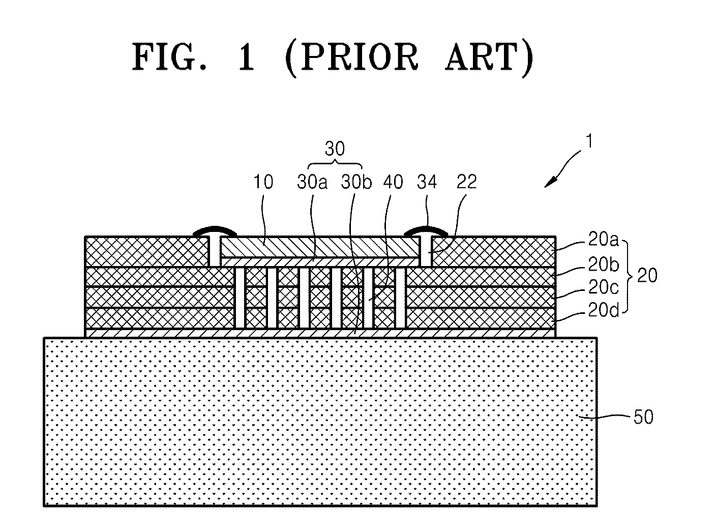
In particular, when a high-heating semiconductor device is manufactured as an LTCC package, a rise in the temperature of the LTCC package caused by heat accumulated in an LTCC substrate becomes problematic.
As the number of layers of the LTCC substrate increases, the above-described problem becomes more serious.
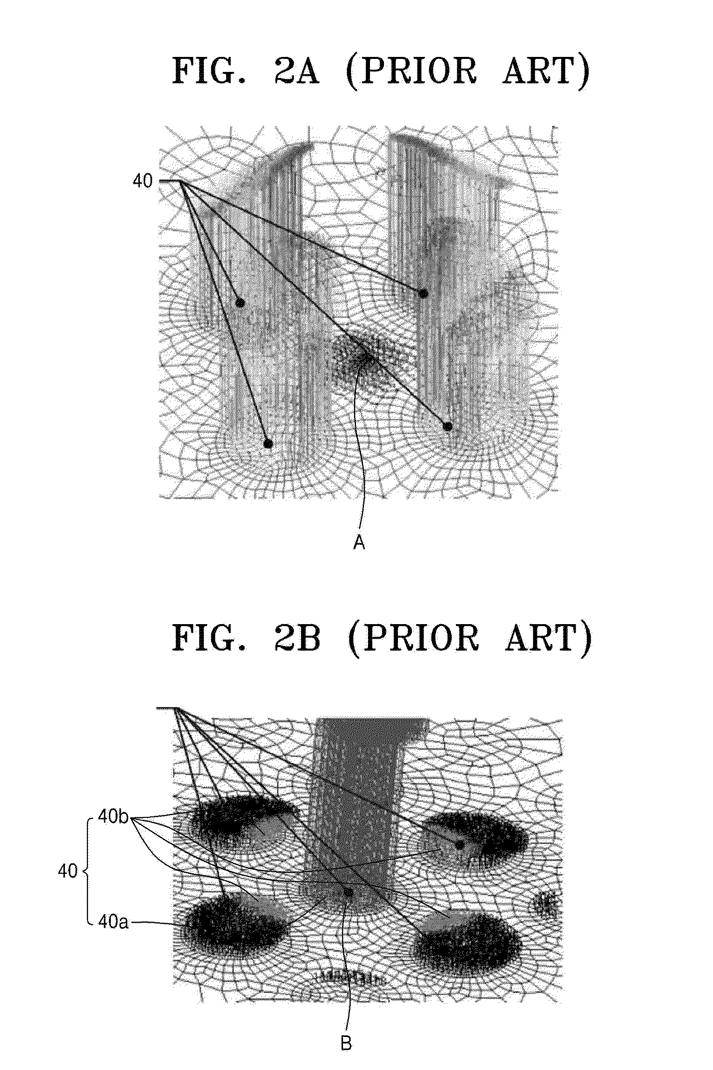
However, heat is hardly transmitted at the heat source A.
However, since the LTCC substrate has a very low thermal conductivity, heat dissipation resistance caused by dissipation of heat from the heat source becomes very high, thus increasing a rise in the temperature of the GaAs MMIC.
However, the size of the thermal vias and an interval between the thermal vias are limited thereto.
Therefore, t

Method used


Image

  • Low-temperature-cofired-ceramic package and method of manufacturing the same
  • Low-temperature-cofired-ceramic package and method of manufacturing the same
  • Low-temperature-cofired-ceramic package and method of manufacturing the same

Examples


Example

[0038]The present invention will now be described more fully hereinafter with reference to the accompanying drawings, in which exemplary embodiments of the invention are shown. This invention may, however, be embodied in different forms and should not be construed as limited to the embodiments set forth herein. Rather, these embodiments are provided so that this disclosure is thorough and complete and fully conveys the scope of the invention to one skilled in the art. It will also be understood that when a layer is referred to as being “on” another layer or substrate, it can be directly on the other layer or substrate or intervening layers may also be present. In the drawings, the thicknesses of layers and regions are exaggerated for clarity. The same reference numerals are used to denote the same elements throughout the specification.

[0039]It will be understood that although the terms first and second are used herein to describe various members, devices, regions, layers, and / or sec...


PUM

PropertyMeasurementUnit
Temperatureaaaaaaaaaa
Electrical resistanceaaaaaaaaaa
Thermal resistanceaaaaaaaaaa

Abstract

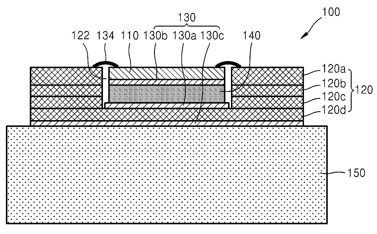
Provided are a low-temperature-cofired-ceramic (LTCC) package and a method of manufacturing the same. The LTCC package includes: an LTCC substrate including a plurality of LTCC layers and a recess in which a device is mounted; a thermal conductive element adhered onto a first LTCC layer exposed by the recess using a first thermal conductive adhesive member; the device adhered onto the thermal conductive element using a second thermal conductive adhesive member; and a connection member for electrically connecting the device with the LTCC substrate. In the LTCC package and the method, portions of the LTCC layers disposed under a high-heating device except a lowermost LTCC layer contacting a heat sink, which correspond to a thermal transmission path, are removed and replaced by a higher thermal conductive material to minimize heat dissipation resistance and heat resistance caused by thermal conduction. Thus, heat resistance and thermal stress between the bottom of the high-heating device and the heat sink can be minimized.

Description

CROSS-REFERENCE TO RELATED PATENT APPLICATION[0001]This application claims the benefit of Korean Patent Application No. 10-2007-0040972, filed on Apr. 26, 2007, in the Korean Intellectual Property Office, the disclosure of which is incorporated herein in its entirety by reference.BACKGROUND OF THE INVENTION[0002]1. Field of the Invention[0003]The present invention relates to a low-temperature-cofired-ceramic (LTCC) package and a method of manufacturing the same, and more particularly, to a low-temperature-cofired-ceramic (LTCC) package having excellent heat dissipation characteristics and a method of manufacturing the same.[0004]The present invention was supported by the Communications, Ocean and Meteorological Satellite program of the Ministry of Information and Communication (MIC) [project No. 2007-S-301, project title: Development of Satellite Communications System for Communications, Ocean and Meteorological Satellite].[0005]2. Description of the Related Art[0006]Low-temperature...

Claims


Application Information

Patent Timeline
IPC IPC(8): H05K7/20B32B38/04
CPCH01L23/13H01L2924/1306H01L23/3735H01L2224/32225H01L2224/48091H01L2224/48227H01L2224/73265H01L2924/01005H01L2924/01013H01L2924/0102H01L2924/01027H01L2924/01029H01L2924/01047H01L2924/01074H01L2924/01079H01L2924/09701H01L2924/10329H01L2924/14H01L2924/1423H01L2924/15153H01L2924/15157H01L2924/1517H01L2924/15787H01L2924/19041H01L2924/19042H01L2924/19043H01L23/3677Y10T156/1056H01L24/32H01L24/48H01L2924/01006H01L2924/01019H01L2924/01033H01L2924/0132H01L2924/00014H01L2924/00H01L2924/00012H01L2924/351H01L24/73H01L2224/2612H01L2224/45099H01L2224/45015H01L2924/207H01L23/36
Inventor KWANK, CHANGSOONOH, YOUN-SUBUHM, MAN-SEOKYOM, IN-BOK
Owner ELECTRONICS & TELECOMM RES INST
Why Eureka
Try Eureka