Enhancement of transition region equalization in a decision feedback equalizer

a transition region and equalizer technology, applied in equalizers, transmission, electrical devices, etc., can solve the problems of affecting the ability of the eye to correctly recover the incoming signal (bit), data receivers may receive significantly distorted signals, and increase the probability of an erroneous recognition of received bits, so as to reduce the unbalance

Active Publication Date: 2010-04-29
STMICROELECTRONICS SRL
View PDF10 Cites 16 Cited by
  • Summary
  • Abstract
  • Description
  • Claims
  • Application Information

AI Technical Summary

Benefits of technology

[0038]The distinct selective early-late detectors may also provide the number of occurrences of the respective monitored specific bit patterns that have contributed to produce the correspondent early-late data provided to the accumulator. In this case, the accumulator may be adapted to momentarily stop accumulation of early-late data of bit patterns other than a bit pattern found to have become significantly less frequent in the bit stream, for as long as new or fresh early-late information for such a momentarily infrequent bit pattern is generated anew, reducing the unbalance.

Problems solved by technology

In serial transmission systems operating at high bit rates over standard pc-boards or coaxial cables, data receivers may receive significantly distorted signals.
Inter-symbol interference (ISI) generated by a limited bandwidth, reflections due to impedance mismatches and other limitations of the transmission media increase the probability of an erroneous recognition of a received bit.
Inside the receiver, a clock and data recovery block (CDR) has the function to reconstruct the clock timing for correctly re-sampling the received data ideally at the middle of the “eye.” However, horizontal (timing) and vertical (amplitude) degradation of the eye negatively affect the CDR capability of correctly recovering the incoming signal (bit).
Upon increasing the operating frequency, the capability of such a linear equalizer acting as a high pass filter matching the reverse of the transfer function of the transmission channel may be inadequate to provide sufficient compensation of the channel frequency losses.
However, this implies that the propagation delays of the flip-flops (of the latches that compose them) and eventually of the multiplexers contribute to the first tap overall feedback delay.

Method used


Image

  • Enhancement of transition region equalization in a decision feedback equalizer
  • Enhancement of transition region equalization in a decision feedback equalizer
  • Enhancement of transition region equalization in a decision feedback equalizer

Examples


Embodiment Construction

[0057]FIG. 9 illustrates how early-late information is obtained in a common circuit block CDR, highlighting how the operation is practically equal to sensing an equality or a difference between the sampled value (sign) with the clock cki+1 and the value (sign) sampled with the clock ckqi when a transition occurs.

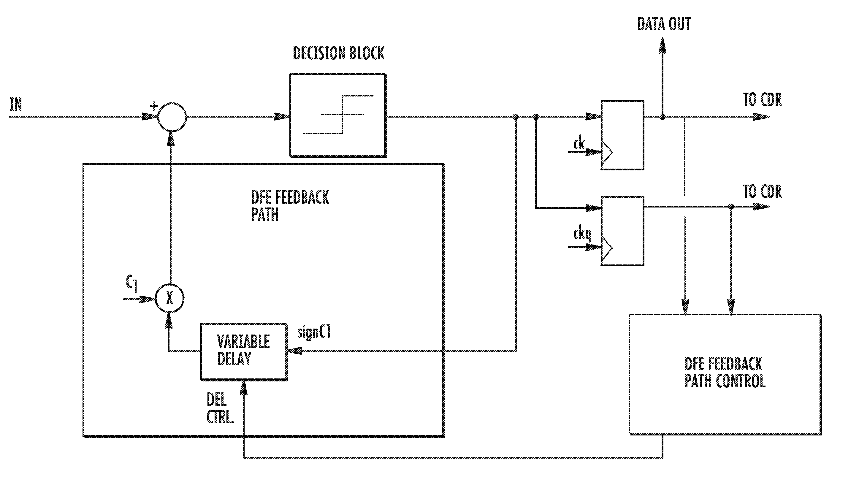
[0058]The main architecture of the enhanced DFE is depicted for an exemplary application to a non-synchronized embodiment of the DFE, as illustrated by the block diagram of FIG. 10. In this illustrated embodiment, a single correction step is contemplated (through a first pre-estimated coefficient).

[0059]The DFE feedback signal path may be represented as receiving the sign value of the previous bit (sign_C1) and feeding back this value to the input of the DFE circuit multiplied by an estimated coefficient c1 after passing through a variable delay circuit VARIABLE DELAY controlled by an appropriate control circuit DFE FEEDBACK PATH CONTROL.

[0060]A sign_C1 signal representing t...


PUM


Abstract

A decision feedback equalizer includes an input path for receiving a bitstream with inter-symbol interference, and a feedback signal path is coupled to the input path for correcting a sampled value of an incoming bit of the bitstream based on inter-symbol interference of a preceding bit. The feedback signal path includes a controllable delay circuit for receiving the preceding bit. A feedback path controller is coupled to the controllable delay circuit to regulate a delay introduced to the preceding bit. The delay is a function of an accumulated value of data of early-late events of a sampling instant of the bitstream for different data pulse patterns.

Description

FIELD OF THE INVENTION [0001]The present invention relates to the equalization of high speed signals to compensate degradation due to a limited bandwidth of the transmission channel and other limitations. In particular, the present invention relates to an add-on improvement of an equalization technique known as decision feedback equalization (DFE).BACKGROUND OF THE INVENTION[0002]In serial transmission systems operating at high bit rates over standard pc-boards or coaxial cables, data receivers may receive significantly distorted signals. Inter-symbol interference (ISI) generated by a limited bandwidth, reflections due to impedance mismatches and other limitations of the transmission media increase the probability of an erroneous recognition of a received bit. For these reasons, it becomes necessary to place, at the receiver input, a circuit to recover the signal before sending it to a re-sampler. Otherwise, the signal arriving at the sampler could be affected by amplitude reduction...

Claims


Application Information

Patent Timeline
Patent Type & Authority Applications(United States)
IPC IPC(8): H04L27/01
CPCH04L25/03063H04L25/0307H04L2025/03579H04L2025/03356H04L25/03885
Inventor POZZONI, MASSIMO
Owner STMICROELECTRONICS SRL
Why Eureka
Try Eureka