Optical access system and optical line terminal

a technology of optical access system and optical line terminal, which is applied in the direction of transmission, multiplex communication, electrical equipment, etc., can solve the problems of reducing reducing the phase ratio of data transmission, and taking a long time to complete the discovery of all the onus b, so as to prevent the efficiency of data transmission from dropping

Inactive Publication Date: 2010-04-29
HITACHI LTD
View PDF14 Cites 12 Cited by
  • Summary
  • Abstract
  • Description
  • Claims
  • Application Information

AI Technical Summary

Benefits of technology

[0020]An optical access system in which the number of the ONUs 20 managed by the OLT 40 is large and the distance between the OLT 40 and the ONUs 20 is long scores high in terms of practicality but has a problem in that it takes long to complete discovery for all the ONUs 20 as described above. Discovery could be completed for all the ONUs 20 in a short period of time by increasing the frequency of executing a discovery phase as shown in the tables 902, 903, and 904 of FIG. 7. However, it would give rise to another problem of the relative reduction in data transmission phase ratio and the resultant lowering in the efficiency of data transmission as illustrated in FIG. 6.
[0022]It is therefore an object of this invention to finish discovery for all ONUs in an optical access system within a given period of time (or to cut short the time required to complete discovery for all ONUs) while preventing the efficiency of data transmission in data transmission phases from dropping.
[0024]According to an embodiment of this invention, discovery can be completed for all ONUs within a given period of time (or the time required to complete discovery for all ONUs can be cut short) and, at the same time, the efficiency of data transmission is prevented from dropping.

Problems solved by technology

An optical access system in which the number of the ONUs 20 managed by the OLT 40 is large and the distance between the OLT 40 and the ONUs 20 is long scores high in terms of practicality but has a problem in that it takes long to complete discovery for all the ONUs 20 as described above.
However, it would give rise to another problem of the relative reduction in data transmission phase ratio and the resultant lowering in the efficiency of data transmission as illustrated in FIG. 6.

Method used


Image

  • Optical access system and optical line terminal
  • Optical access system and optical line terminal
  • Optical access system and optical line terminal

Examples


first embodiment

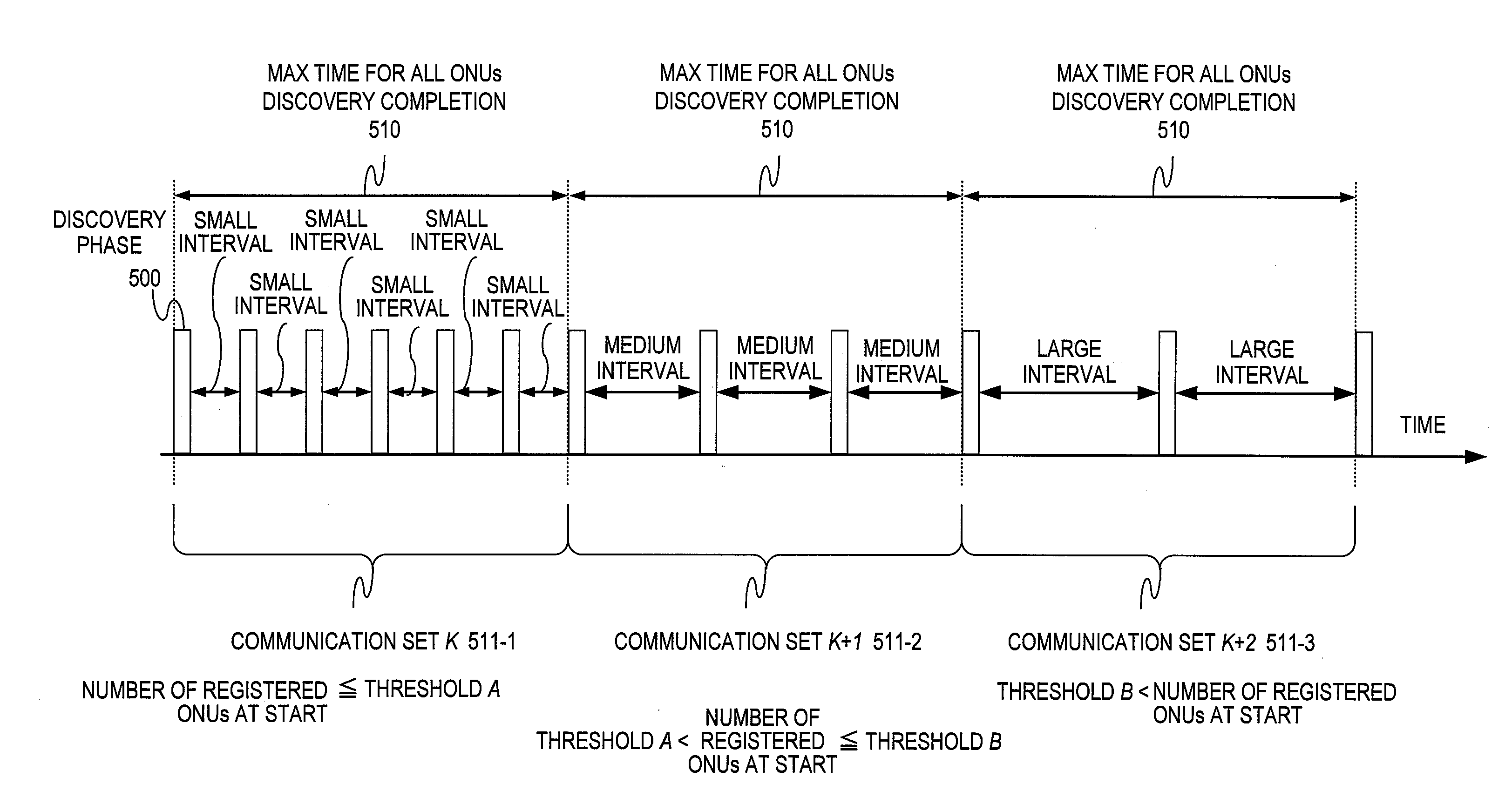
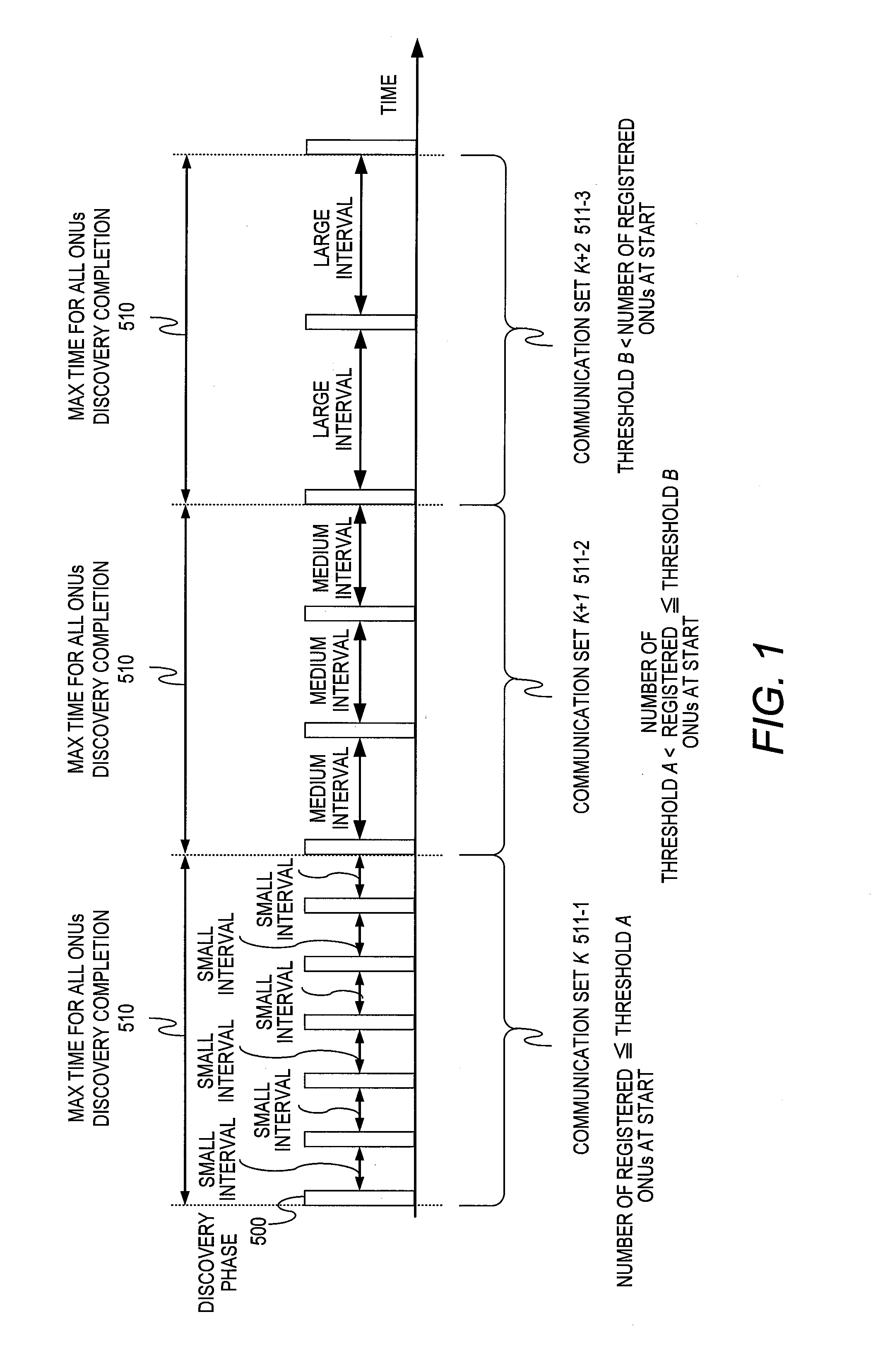
[0047]Described in a first embodiment of this invention is a method of cutting short the time required to complete discovery for all ONUs by dynamically changing the time interval between discovery phases (discovery phase frequency).

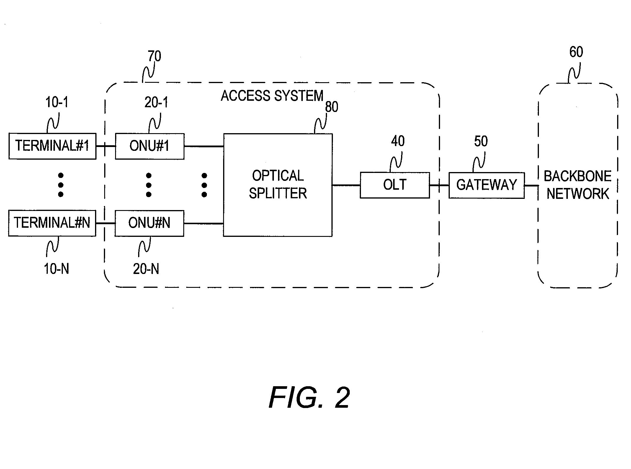
[0048]FIG. 2 is a diagram illustrating a configuration example of an optical network system according to the first embodiment of this invention.

[0049]An optical access system 70 has the optical network units (ONUs) 20, the optical splitter 80, and the optical line terminal (OLT) 40.

[0050]The optical access system 70 has as many optical network units (ONUs) 20 as the number of users, and the plurality of ONUs 20 are respectively connected to user terminals 10 to communicate with the user terminals 10. The optical line terminal (OLT) 40 is connected to the gateway 50 to communicate with the backbone network 60 via the gateway 50. The plurality of ONUs 20 and the OLT 40 are connected to each other via the optical splitter 80, which is a passive device requi...

second embodiment

[0080]A second embodiment of this invention is described next which deals with a method of cutting short the time required to complete discovery for all the ONUs 20 by dynamically changing the length of a single discovery phase, instead of changing the time interval between discovery phases.

[0081]An optical access system of the second embodiment has the same configuration as that of the optical access system of the first embodiment which is equipped with the optical splitter 80 as described above with reference to FIG. 2. The second embodiment is also applicable to the optical access system of FIG. 14 which has the active optical switch 30 instead of the optical splitter 80.

[0082]FIG. 12 is a timing chart illustrating an example of changing the length of time of executing a discovery phase according to the second embodiment.

[0083]In the example of FIG. 12, two different thresholds A and B are used as a threshold for the number of the registered ONUs 20 managed by the OLT 40. The thr...

third embodiment

[0100]A third embodiment of this invention is described next which deals with a method of cutting short the time required to complete discovery for all the ONUs 20 that have not been registered in the OLT 40 and that are requesting connection in the optical access system of FIG. 14, where the optical switch 30 detects optical signals from the ONUs 20. The description in the third embodiment focuses on differences from the first and second embodiments described above.

[0101]FIG. 16 is a block diagram illustrating a configuration example of the optical switch 30 of the third embodiment.

[0102]The optical switch 30 of the third embodiment is characterized by having a power monitor 313 for detecting the presence or absence of an optical signal in the upstream optical switch 312.

[0103]The optical switch 30 has the wavelength multiplexer, demultiplexer 360, the wavelength multiplexer, demultiplexer 361, an optical splitter 340, the downstream optical switch 311, the upstream optical switch ...


PUM


Abstract

Provided is an optical access system comprising: an optical line terminal connected to another network; a plurality of optical network units, each connected to a user terminal; and at least one of an optical switching unit and an optical splitter, which is installed between the optical line terminal and the plurality of optical network units. The optical line terminal allocates a length of time to a discovery phase for detecting the plurality of optical network units, and a length of time to data transmission phases for transferring data from the plurality of optical network units; and changes a ratio of the length of time of the discovery phase to the length of time of the data transmission phases so that the length of time of the discovery phase is shortened in the case where a number of the optical network units that are registered in the optical line terminal increase.

Description

CLAIM OF PRIORITY[0001]The present application claims priority from Japanese patent application JP 2008-274085 filed on Oct. 24, 2008, the content of which is hereby incorporated by reference into this application.BACKGROUND OF THE INVENTION[0002]This invention relates to an optical access system and, more particularly, to a technique of executing discovery of optical network units quickly.[0003]The recent propagation of Fiber To The Home (FTTH) which uses an optical fiber has increased the speed of access networks. A representative example of FTTH is a passive optical network (PON) system.[0004]A PON system has, as illustrated in FIG. 2, a plurality of (N) optical network units (ONU) 20, which communicate with user terminals 10, and an optical line terminal (OLT) 40, which communicates with a backbone network 60 via a gateway 50. The plurality of ONUs 20 and the OLT 40 are connected to each other via an optical splitter 80, which is a passive device requiring no power feeding. The ...

Claims


Application Information

Patent Timeline
Patent Type & Authority Applications(United States)
IPC IPC(8): H04J14/00
CPCH04J2203/0058H04L43/0864H04Q2011/0088H04Q2011/0079H04Q11/0067
Inventor OKUNO, MICHITAKAWAKAYAMA, KOJISAKAMOTO, KENICHIIKEDA, HIROKI
Owner HITACHI LTD
Why Eureka
Try Eureka