Apparatus and Method for Measuring Water Quality in a Water Distribution System

a technology of water distribution system and apparatus, applied in the field of apparatus and methods for measuring water quality in water distribution system, can solve the problems of not being economically or environmentally practical to install these systems at end point locations, and the methodology cannot be used at the end points of a utility distribution network, so as to reduce the high cost of various sensors

Inactive Publication Date: 2010-04-29
BADGER METER
View PDF2 Cites 15 Cited by
  • Summary
  • Abstract
  • Description
  • Claims
  • Application Information

AI Technical Summary

Benefits of technology

[0006]In the system of the invention, at least one sensor is associated with each end point (meter) to measure a different biological, chemical or environmental parameter within the specified region of the water distribution network. While more than one sensor might be utilized at a particular meter, it is an objective of the invention to reduce the high cost of the various sensors that are necessary by distributing them among the end points in a zone of a water distribution system. Sensors can also be located at zone meters to monitor a specific parameter for a zone of the water distribution system, with different sensors being distributed to different zones.
[0007]A water utility distribution system can be protected from a wide array of potential biological and chemical contaminants and environmental parameters and can be economically deployed using the present invention, as there is only one parameter sensed per meter. It also provides early automatic detection of potential contamination events.

Problems solved by technology

Current methods and practices for sensing biological and chemical parameters, as well as environmental parameters such as residual chlorine, TOC (total organic carbon), turbidity, pressure, and others, involve systems with expensive sensors located at special stations within a water system.
This methodology cannot be used at the end points of a utility distribution network.
It has not been economically or environmentally practical to install these systems at end point locations.
If this were to occur, it is probable the current technologies and equipment would not detect the contamination event.

Method used


Image

  • Apparatus and Method for Measuring Water Quality in a Water Distribution System
  • Apparatus and Method for Measuring Water Quality in a Water Distribution System
  • Apparatus and Method for Measuring Water Quality in a Water Distribution System

Examples


Embodiment Construction

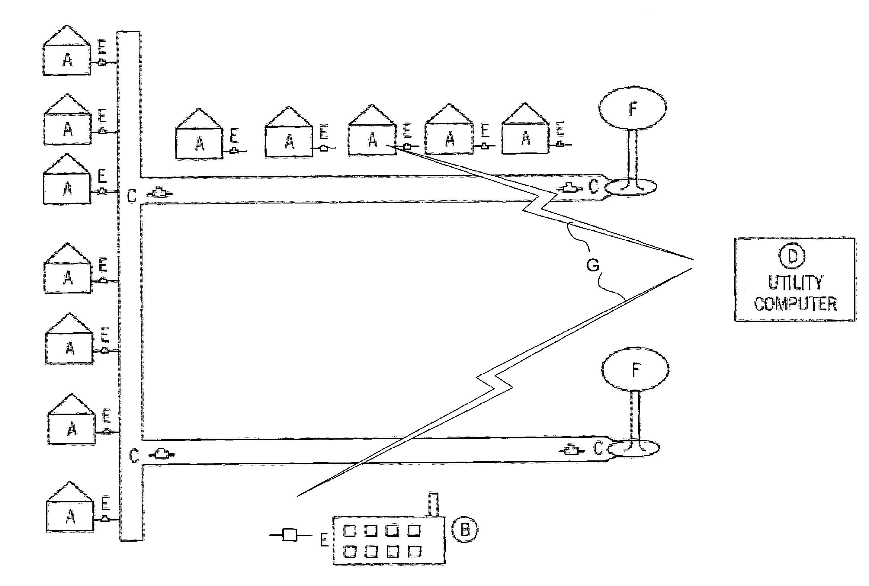
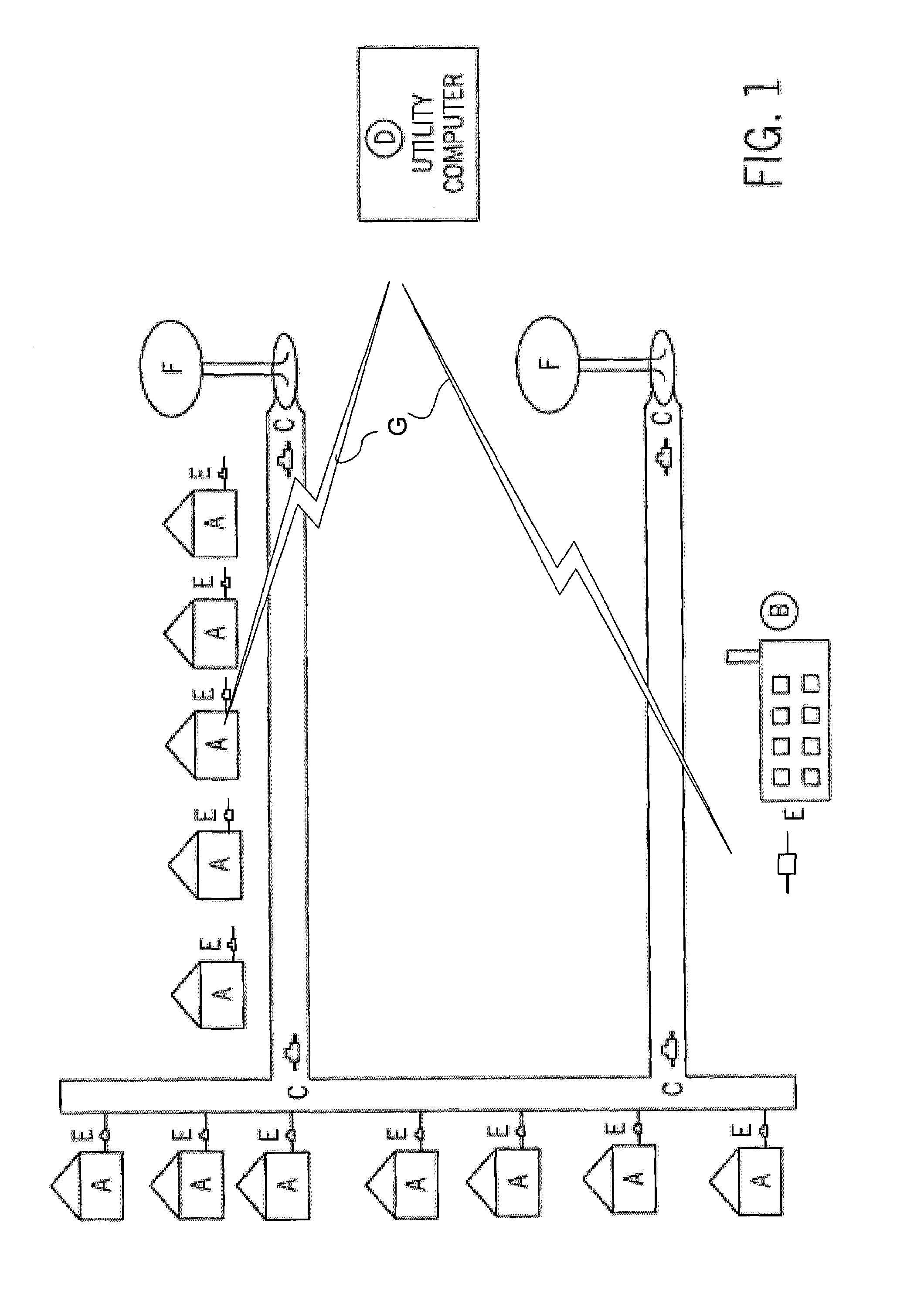
[0012]FIG. 1 illustrates a subsection of a water utility distribution system, where “A” designates individual single-unit end points within the distribution system. “B” designates individual commercial, industrial or multi-unit end points within the distribution system. “C” designates zone water meters that measure the quantity or quality of water distributed to one zone or section of the distribution system. “D” designates the utility main office computer system. “E” designates the end point meters that measure the quantity or quality of water distributed to a single Residential, commercial or industrial end point. “F” designates a water storage facility (tanks or vaults) for water used within the distribution system. And, “G” designates a wireless network such as SMS, GPRS, GSM, private radio network, PSTN, or wireless Internet.

[0013]Currently, water utilities must report several parameters to a governmental environmental protection agency on a quarterly basis. These parameters in...


PUM

PropertyMeasurementUnit
electricalaaaaaaaaaa
radio frequency meteringaaaaaaaaaa
chemicalaaaaaaaaaa

Abstract

A system for monitoring water quality in a water distribution system having a plurality of metering end points (E) for measuring consumption includes a plurality of chemical biological and environmental sensors (S1, S2) disposed in a distribution system near or within the distribution end points (A, B), with the sensors (S1, S2) generating electrical signals through a network (G) that can be processed and communicated to a collection station (D) from the metering end points (E).

Description

CROSS REFERENCE TO RELATED APPLICATION[0001]The benefit of priority based on U.S. Prov. Pat. App. No. 60 / 959,833, filed Jul. 17, 2007, is claimed herein.TECHNICAL FIELD[0002]The field of the invention is water distribution systems for supplying single-unit residential, multi-unit residential, commercial and industrial customers with water from a municipal or district utility provider. The invention also relates to instruments for sensing water quality.BACKGROUND OF THE INVENTION[0003]Current methods and practices for sensing biological and chemical parameters, as well as environmental parameters such as residual chlorine, TOC (total organic carbon), turbidity, pressure, and others, involve systems with expensive sensors located at special stations within a water system. Many systems currently available on the market to test for environmental parameters require a waste stream, sometimes toxic, as a byproduct of the testing. This methodology cannot be used at the end points of a utili...

Claims


Application Information

Patent Timeline
Patent Type & Authority Applications(United States)
IPC IPC(8): G01N33/00G01F1/56
CPCG01N33/18Y10T436/20G01N35/00871G01F1/56
Inventor MEEUSEN, RICHARD A.GOMEZ, GREGORY M.FABER, J. DONALDWEBB, DENNIS J.ZANDRON, DANIEL D.LAZAR, MARK
Owner BADGER METER
Why Eureka
Try Eureka