Transcaval mesenteric venous anastomosis and access system

a transcaval mesenteric vein and access system technology, applied in the field of transcaval mesenteric vein anastomosis and access system, can solve the problems of fatal bleeding, increased blood pressure in the portal system, abdominal swelling, etc., and achieve the effect of safe and effective treatment of portal hypertension

Inactive Publication Date: 2010-04-29
THE JOHN HOPKINS UNIV SCHOOL OF MEDICINE
View PDF5 Cites 24 Cited by
  • Summary
  • Abstract
  • Description
  • Claims
  • Application Information

AI Technical Summary

Benefits of technology

[0014]Accordingly, one advantage of the present invention is that it enables safe and repeated access to the mesenteric system.
[0015]Another advantage of the present invention is that it provides a safe, more effective treatment for portal hypertension.
[0016]Additional advantages of the invention will be set forth in the description that follows, and in part will be apparent from the description, or may be learned by practice of the invention. The advantages of the invention will be realized and attained by the structure pointed out in the written description and claims hereof as well as the appended drawings.
[0017]To achieve these and other advantages in accordance with the present invention, a device for creating an anastomosis between two vascular lumens is provided, which comprises a first flange part; a second flange part; a flow lumen part disposed between the first flange part and the second flange part; and a valve part disposed on the first flange part.
[0018]In another aspect of the present invention, the aforementioned and other advantages are achieved by a device for creating an anastomosis between two vascular lumens, which comprises a first flange part; a second flange part; and a flow lumen part disposed between the first flange part and the second flange part, wherein the first flange part, the second flange part, and the flow lumen part include a wire having a memory shape material.
[0019]In another aspect of the present invention, the aforementioned and other advantages are achieved by a method for creating an anastomosis between a first and a second vascular lumen. The method comprises inserting a catheter into the first vascular lumen; guiding the catheter to a desired location for the anastomosis; puncturing the first vascular lumen; puncturing the second vascular lumen; inserting the catheter into the second vascular lumen; deploying a distal flange part of an anastomosis device within the second vascular lumen; bringing the second vascular lumen into apposition with the first vascular lumen; and deploying a proximal flange part of the anastomosis device within the first vascular lumen.

Problems solved by technology

There are numerous health problems related to the mesenteric system that are among the leading causes of death in the United States, including diabetes, pancreatic cancer, liver cancer, and liver cirrhosis.
Cirrhosis generally leads to portal hypertension, in which liver scar tissue prevents blood flow through the liver, which in turn increases blood pressure in the portal system.
Left unchecked, portal hypertension may cause abdominal swelling, damage other organs in the portal system, and may cause fatal bleeding.
Because of limited availability of donor livers and technical surgical expertise, transplantation is not a viable option for the majority of candidates.
Surgeries to create portosystemic shunts are invasive and generally have high complication rates.
Further, the TIPS procedure is generally performed without direct visualization of the portal venous system, which may incur complications such as traversal of the liver capsule and creation of fistulous tracts from the shunt to the hepatic artery of bile ducts.
The inherent difficulty of creating portosystemic and TIP shunts precludes less invasive procedures, such as percutaneous procedures.
Related art treatments for liver cancer, pancreatic cancer, diabetes (via islet cell transplantation) are difficult because they require access the mesenteric venous system directly through the liver.
This has risks of complications.
Further, related art treatments only allow temporary access to the mesenteric system.

Method used


Image

  • Transcaval mesenteric venous anastomosis and access system
  • Transcaval mesenteric venous anastomosis and access system
  • Transcaval mesenteric venous anastomosis and access system

Examples


first embodiment

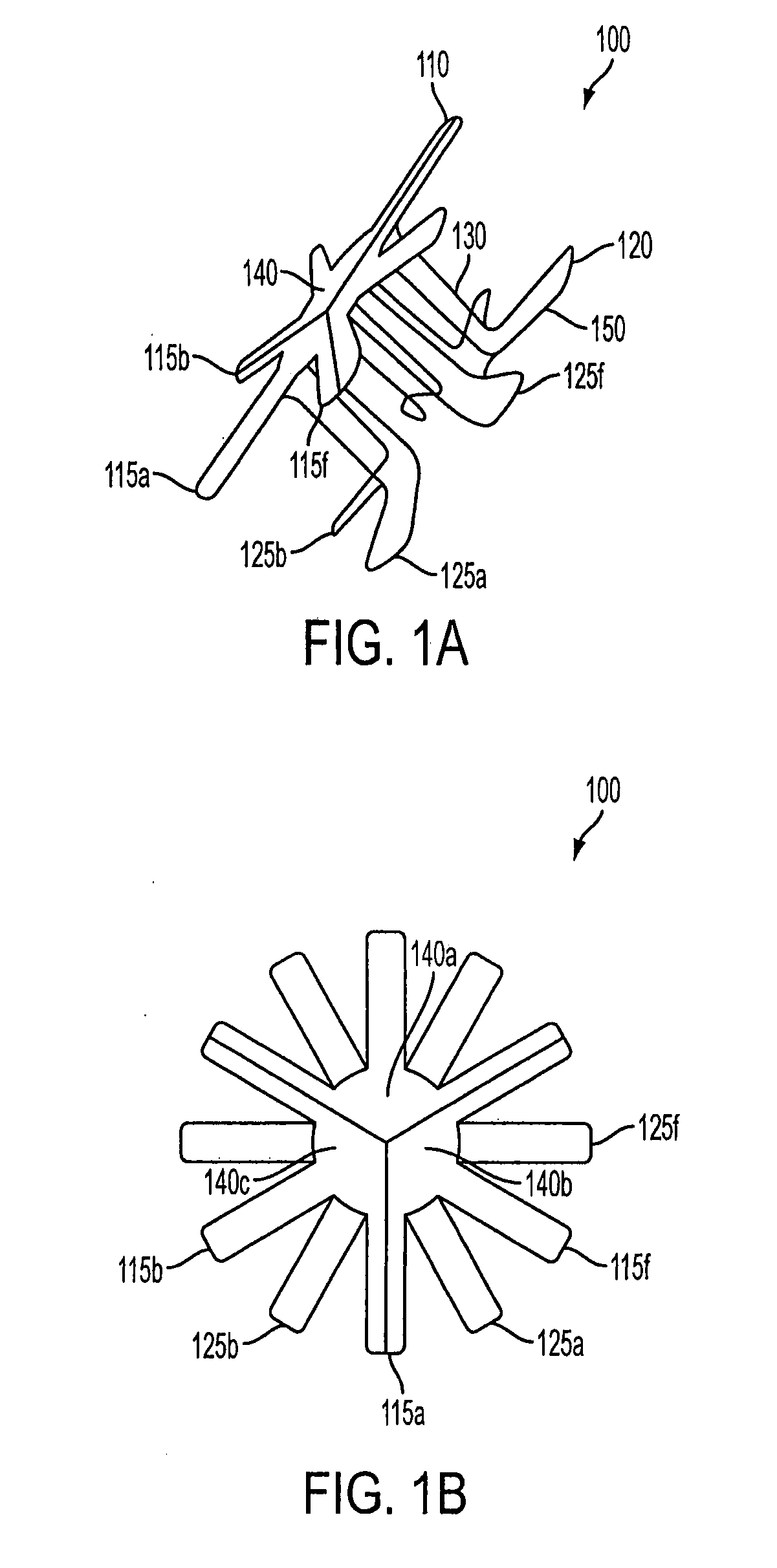
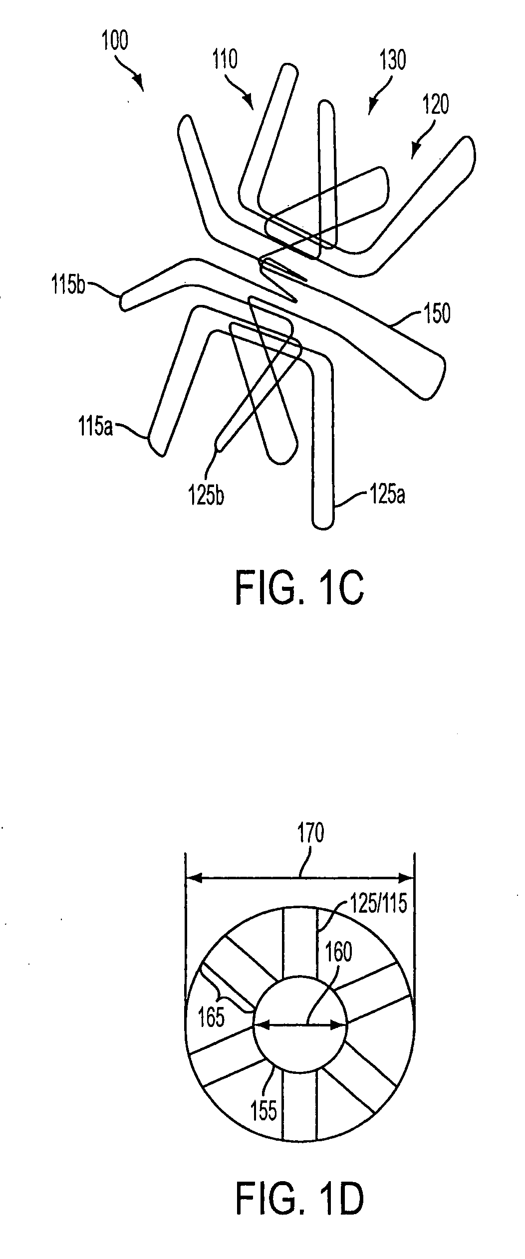
[0035]FIG. 1A illustrates an anastomosis device 100 according to the present invention. Anastmosis device 100 includes a proximal flange part 110, a distal flange part 120, and a flow lumen part 130 between proximal flange part 110 and distal flange part 120. Proximal flange part 110 has a plurality of proximal radial struts 115a-f, and distal flange part 120 has a plurality of distal radial struts 125a-f. Disposed on the plurality of proximal radial struts 115a-f is a valve part 140, which may include a plurality of leaflet parts 140a-c.

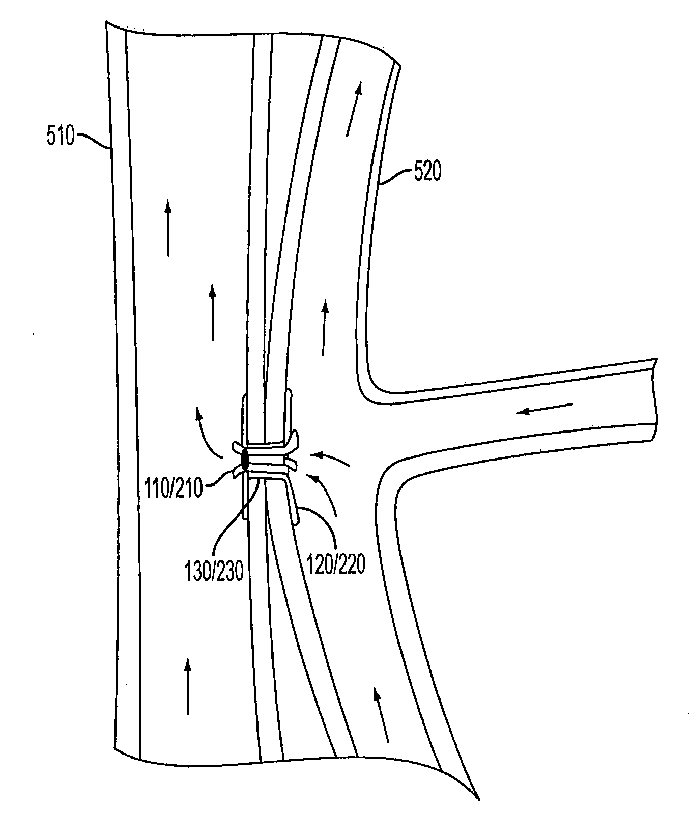
[0036]Proximal flange part 110 and distal flange part 120 are used to hold the vascular lumens apposed to each other, as illustrated in greater detail below. Flow lumen part 130 provides a flow conduit for blood (or other fluids) and provides a path for a surgeon to advance an interventional diagnostic or therapeutic device.

[0037]Proximal radial struts 115a-f define an aperture (not shown) in a center portion of proximal flange part 110. Distal rad...

second embodiment

[0047]FIGS. 2A and 2B illustrate an exemplary anastomosis device 200 according to the present invention. Exemplary anastomosis device 200 may be substantially similar to anastomosis device 100, but with a different valve part 240. Anastomosis device 200 may also have a plurality of capacitors (not shown) substantially similar to capacitors 180 of anastomosis device 100. Valve part 240 includes a spiral configuration of wire, such as Nitinol. More specifically, valve part 240 may have a superelastic coil that forms a seal. Valve part 240 is preferably disposed on the proximal flange part 210, the distal flange part 220, or both, as explained above.

[0048]If valve part 240 is disposed on proximal flange part 210, the proximal radial struts 215a-f may have a covering substantially similar to leaflets 140a-c of the first embodiment. The covering is to prevent leakage around valve part 240. Similarly, if valve part 240 is disposed on distal flange part 220, then distal radial struts 225a-...


PUM


Abstract

Disclosed is a system for creating an anastomosis between the inferior vena cava (IVC) and the mesenteric portal vein. The system includes an anastomosis device and a catheter. The anastomosis device brings the IVC and the portal vein into apposition. The resulting anastomosis enables treatment for portal hypertension as well as provides repeated and easy access to the portal system for direct delivery of therapeutic agents to portal organs. The anastomosis device has a proximal flange part, a distal flange part, a flow lumen between them. The proximal and distal flange parts include a plurality of radial struts. A valve part is disposed on one or both of the proximal and distal flange parts. The anastomosis device is made of a memory shape material. The catheter contains a collapsed anastomosis device for insertion and has one or more RF antennas to make the catheter visible under MRI guidance.

Description

[0001]This application claims the benefit of U.S. Provisional Patent Application No. 60 / 678,339 filed on May 6, 2005, which is hereby incorporated by reference for all purposes as if fully set forth herein.[0002]The research and development effort associated with the subject matter of this patent application was supported by the National Institutes of Health (NIH) under Grants NIH R01 57483 and 1K08EB004348-01.BACKGROUND OF THE INVENTION[0003]1. Field of the Invention[0004]The present invention generally relates to devices and systems for percutaneously forming an anastomosis between two vascular lumens or two anatomical chambers, wherein one of the lumens or chambers is not directly accessible by conventional percutaneous interventional procedures. More particularly, the present invention relates to devices and systems for forming an anastomosis between the inferior vena cava (IVC) and the portal vein of the mesenteric venous system, whereby the anastomosis enables periodic and rel...

Claims


Application Information

Patent Timeline
Patent Type & Authority Applications(United States)
IPC IPC(8): A61B17/00
CPCA61B17/11A61B17/3498A61B2017/00252A61B2019/5454A61B2017/1107A61B2017/1139A61B2017/22077A61B2017/1103A61B2090/3954
Inventor AREPALLY, ARAVINDKARMARKAR, PARAG V.DI, QIANATALAR, ERGIN
Owner THE JOHN HOPKINS UNIV SCHOOL OF MEDICINE
Why Eureka
Try Eureka