
Mechanical anastomosis system for hollow structures

a hollow structure and mechanical technology, applied in the field of hollow structure mechanical anastomosis system, can solve the problems of inability to make mechanical anastomosis, inability to achieve the effect of mechanical anastomosis, and a number of side effects of the heart-lung machine for the patient, so as to achieve the effect of convenient making of mechanical anastomosis

Inactive Publication Date: 2010-04-29
INNOVATIVE INTERVENTIONAL TECH
View PDF23 Cites 2 Cited by
  • Summary
  • Abstract
  • Description
  • Claims
  • Application Information

AI Technical Summary

Benefits of technology

[0009]The object of the present invention is to provide a system for making anastomoses between hollow structures by mechanical means, which will make it easier to make mechanical anastomoses.
[0011]The system according to the invention makes it possible to effect an anastomosis faster and more easily by placing an annular or tubular element comprising joining means with the aid of said applicator, which joining means are also activated by said applicator, in such a manner that the anastomosis is made.

Problems solved by technology

This is not always possible, however.
Thus, the use of the heart-lung machine has a number of side effects for the patient, as a result of which recovery following surgery takes more time.
Moreover, the necessary disposables for the heart-lung machine are costly.
The drawbacks of said method are the fact that only a limited number of places on the heart can be reached and the fact that part of the heart is temporarily anemic, because it is necessary to stop the circulation through the blood vessel to be treated for 8-15 minutes.

Method used


Image

  • Mechanical anastomosis system for hollow structures
  • Mechanical anastomosis system for hollow structures
  • Mechanical anastomosis system for hollow structures

Examples


first embodiment

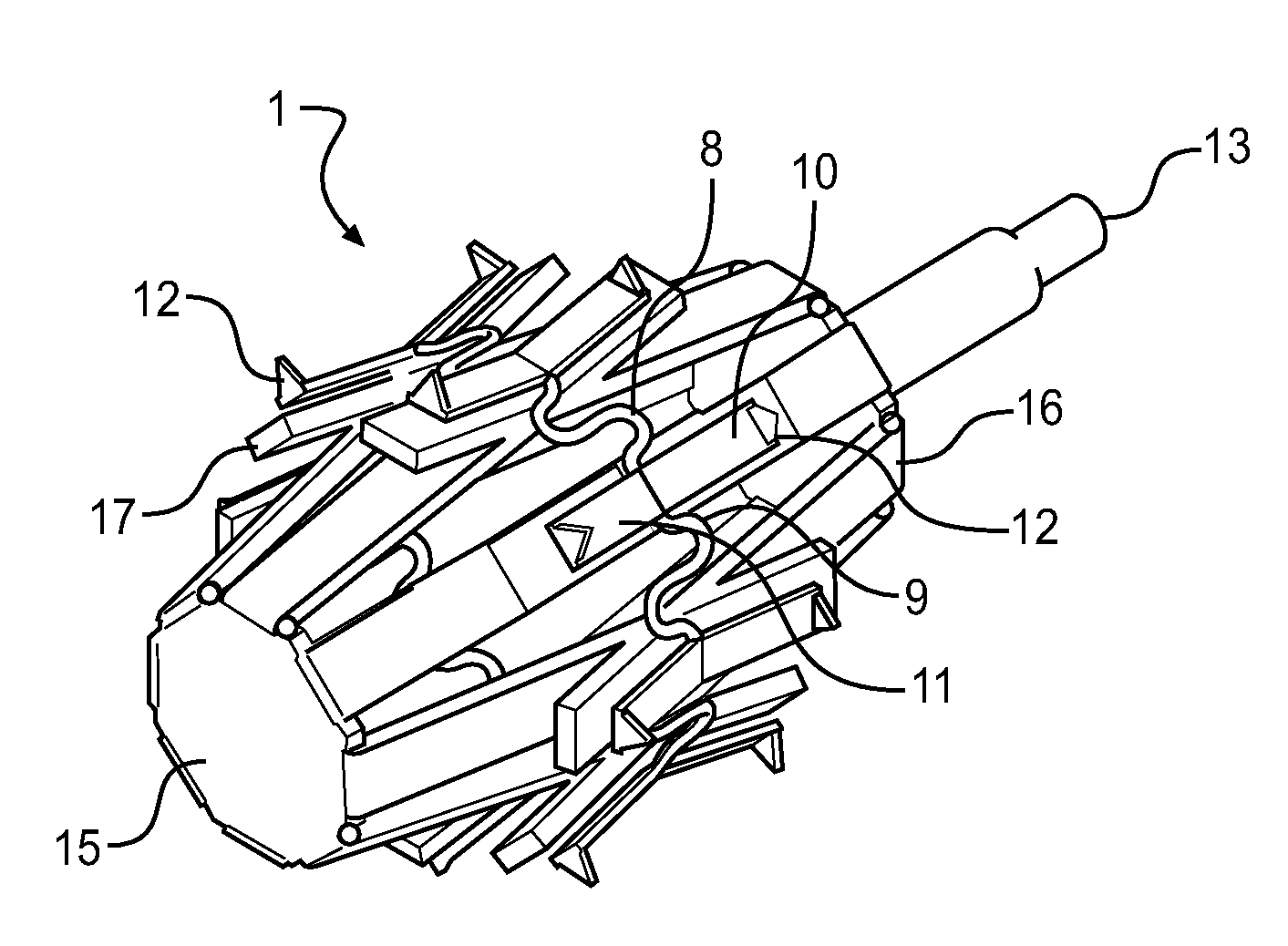
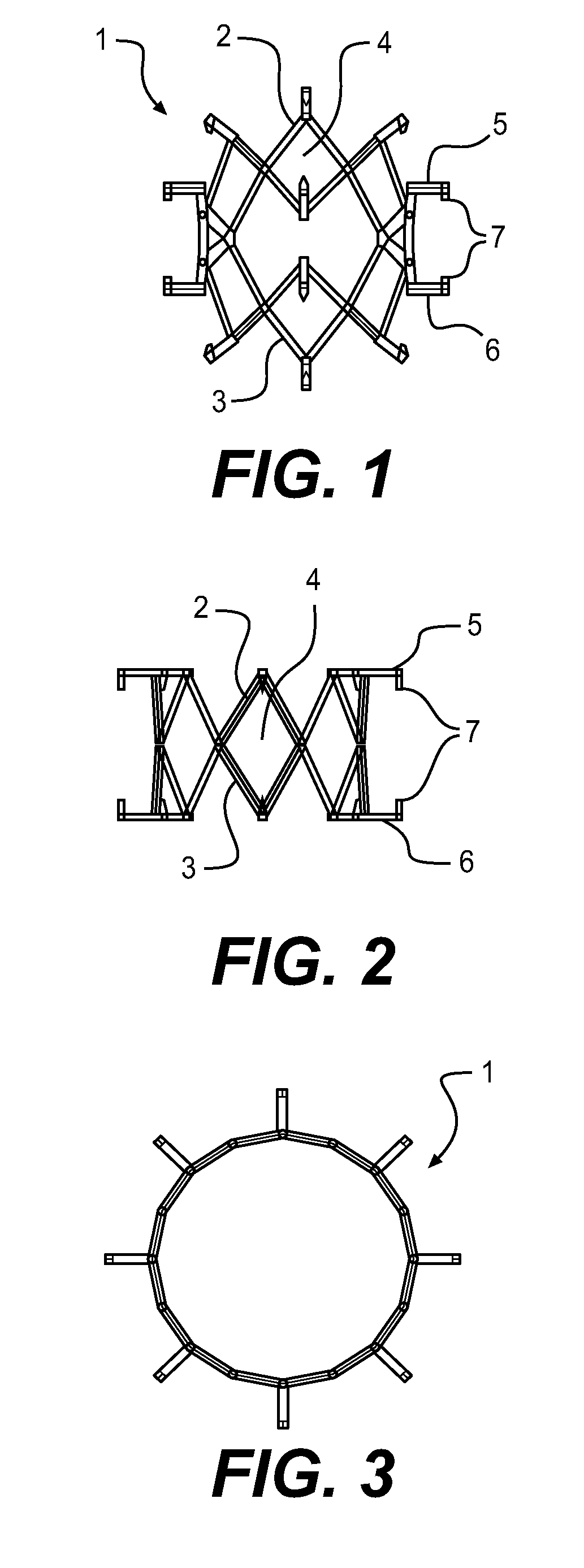
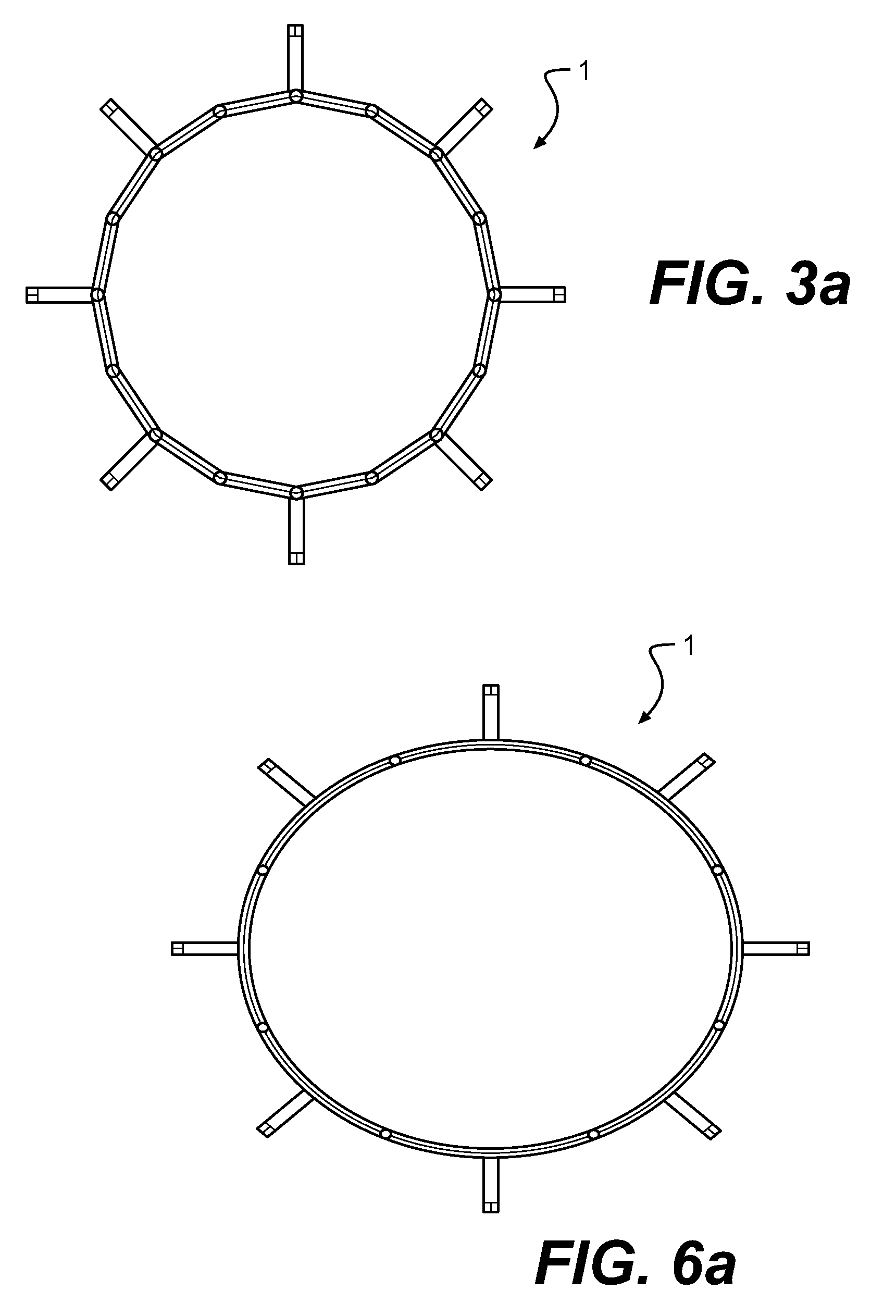
[0044]FIGS. 1-6 show a device for making anastomoses between hollow structures, in particular arteries or veins, by mechanical means.

[0045]In the present case, the device is a one-piece tubular or annular element 1, which is made of a biocompatible and plastically deformable material, for example a tantalum alloy or another material used in medical technology. Annular element 1 may be considered to be an assembly of two zigzag-like elongated elements 2 and 3 which extend substantially in circumferential direction but not along the contour line, which elements are interconnected at the facing vertices, thus forming a ring of diamond-shaped structures 4. Present on the vertices of the zigzag-like elements 2, 3 that face away from each other are pin-shaped elements 5, 6, which are provided with sharp tips 7 at their ends facing away from annular element 1, wherein the tips 7 of two associated pin-shaped elements 5, 6 forming a pair are directed towards each other. The pin-shaped elemen...

third embodiment

[0056]FIGS. 16-21 show the device according to the invention, which can be used for intraluminal placement in the case of a side-to-side anastomosis, but in particular also for extraluminal placement in the case of an end-to-side anastomosis.

[0057]In this case, annular element 1 consists of a circular, elongated element 19, which is circumferentially provided in a number of places with pin-shaped elements 20, which axially project to one side from said elongated element 19. The pins may be provided with points 21 thereby, whilst the pin-shaped elements 20 may be flat, or possibly round or the like. As is shown in FIGS. 19-21, the pin-shaped elements 20 are in large measure bent radially outwards in the joining position of the device, but they may also be bent tangentially.

[0058]In order to be able to deform the pin-shaped elements 20 from the starting position to the joining position, the applicator according to FIGS. 22-24 is provided. Also this applicator is provided with a shank-...


PUM


Abstract

A system for making anastomoses between hollow structures by mechanical means is provided with a device in the shape of an annular or tubular element comprising circumferentially provided means, such as pin-shaped elements, for joining the abutting walls of the hollow structures together. An applicator is intended for moving said annular or tubular element in position and activating the joining means thereof, so as to make the anastomosis. Possibly, intraluminal joining means can be inserted without using an annular or tubular element.

Description

RELATED APPLICATION DATA[0001]This application is a divisional of U.S. patent application Ser. No. 10 / 162,261, filed on Jun. 4, 2002, currently pending, which, in turn, is a divisional of U.S. patent application Ser. No. 09 / 529,900, filed on Apr. 21, 2000, now U.S. Pat. No. 6,485,496, issued on Nov. 26, 2002, which, in turn is a 371 continuation of International application no. PCT / NL98 / 00605, filed on Oct. 22, 1998, designating the United States of America.BACKGROUND OF THE INVENTION[0002]1. Field of the Invention[0003]The present invention relates to a system for making anastomoses between hollow structures by mechanical means, and also to a device and an applicator for use therewith.[0004]2. Description of the State of the Art[0005]Such a system may for example be used when making a bypass past narrowings or occlusions of arteries caused by arteriosclerosis. There are now various possibilities of remedying such constrictions or occlusions.[0006]If the constriction or occlusion ta...

Claims


Application Information

Patent Timeline
Patent Type & Authority Applications(United States)
IPC IPC(8): A61B17/11A61B17/064A61B17/08A61B17/115
CPCA61B17/0644A61B17/08A61B17/11A61B17/115Y10S227/902A61B2017/1107A61B2017/1135A61B2017/1139Y10S227/901A61B2017/0641
Inventor SUYKER, WILHELMUS JOSEPH LEONARDUSSUYKER, PAULUS THOMAS WILHELMUS
Owner INNOVATIVE INTERVENTIONAL TECH
Learn More