Device for detecting a flaw in a component

a technology for components and flaws, applied in the field of devices for detecting flaws in components, can solve the problems of insufficient contribution of sound energy to flaw detection, negative effect on flaw assessment,

Inactive Publication Date: 2010-05-06
AIRBUS OPERATIONS GMBH
View PDF15 Cites 15 Cited by
  • Summary
  • Abstract
  • Description
  • Claims
  • Application Information

AI Technical Summary

Benefits of technology

[0008]It is therefore the object of the invention to provide a device with which flaws in

Problems solved by technology

In contrast with the above, the conventional perpendicular alignment of the probe, and thus the sound beam emitted by the probe, means that the majority of the sound energy is directed through the hole without interacti

Method used


Image

  • Device for detecting a flaw in a component
  • Device for detecting a flaw in a component
  • Device for detecting a flaw in a component

Examples


Embodiment Construction

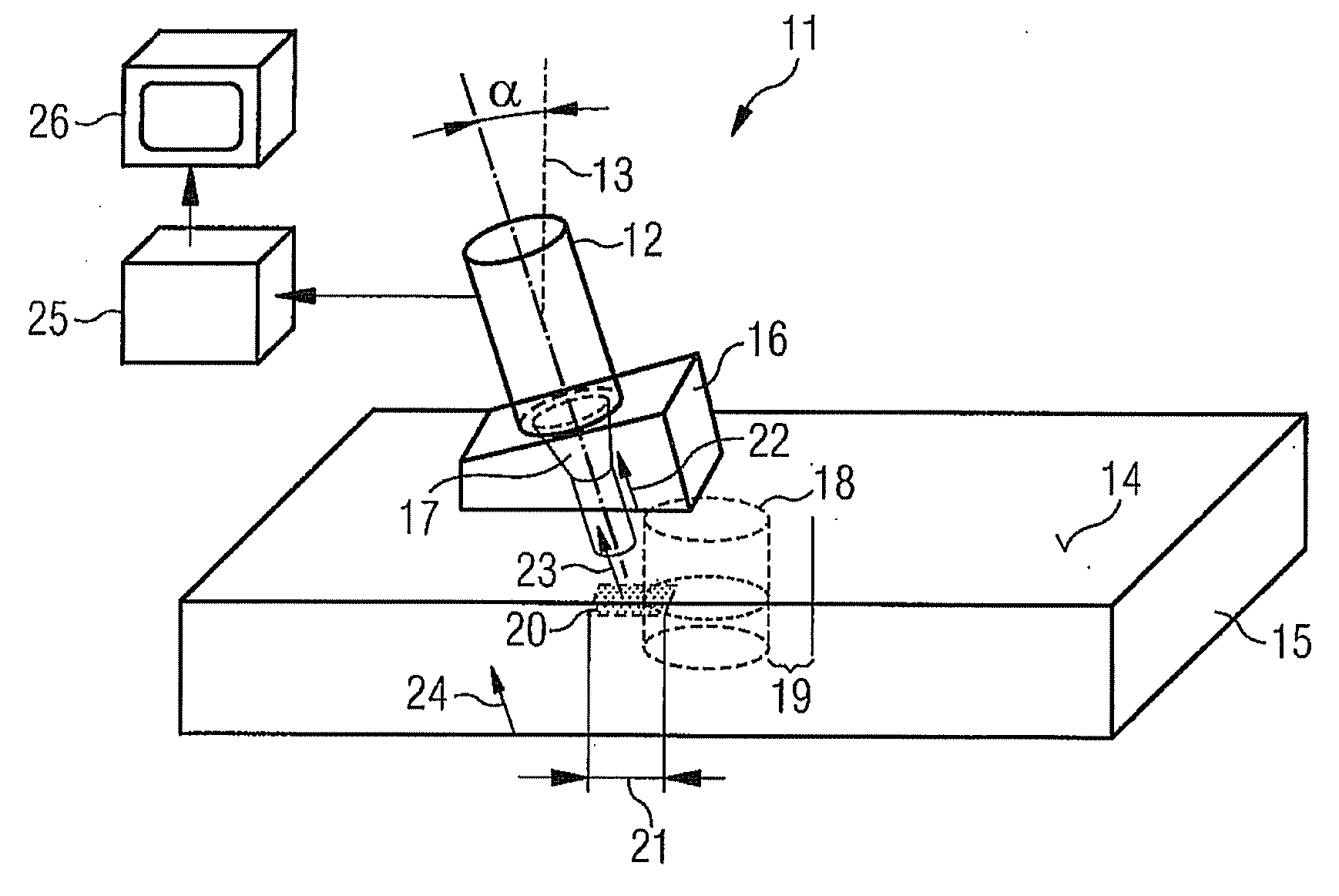
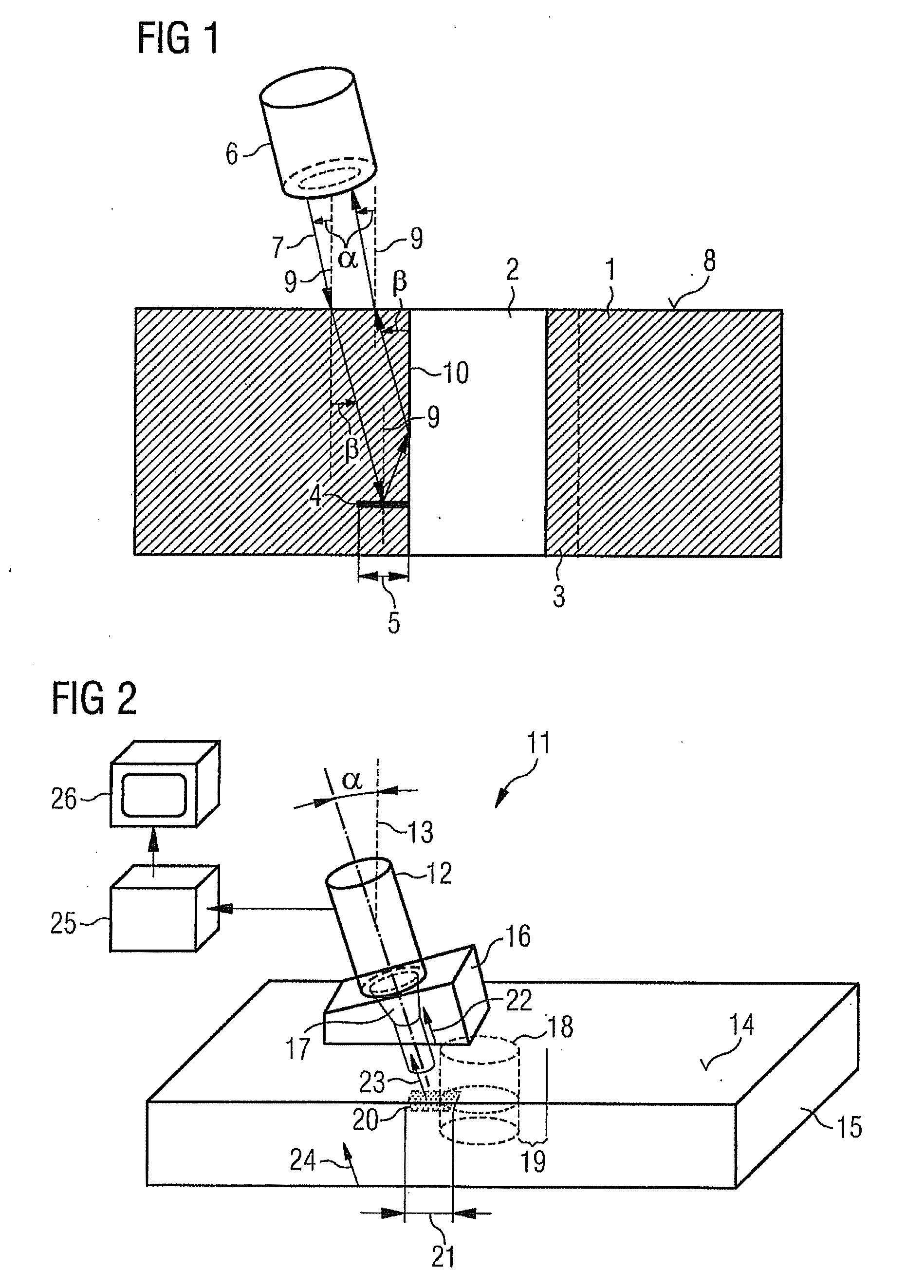
[0052]FIG. 1 is a schematic view of the operation of a device formed according to the invention.

[0053]A cylindrical hole 2 is formed in a component 1. The component 1 is preferably any composite component generally formed from a carbon-fibre-reinforced epoxy resin. There is delamination 4 to be detected having a width 5 in a bearing region 3 of the hole 2. The term “delamination” refers to a region in which reinforcing fibre layers have become detached or separated from the surrounding polymer matrix. These air-filled delamination regions may be formed during the process of manufacturing the component 1 or when the holes are formed. In both cases, the mechanical loading capacity of a connection between the component 1 and an attachment, formed for example by introducing bolts or rivets into the hole 1, is detrimentally affected, so therefore delamination in the region of holes in composite components must be able to be reliably detected in a continuous test process.

[0054]Ultrasound ...


PUM


Abstract

The invention relates to a device for detecting a flaw in a fibre-reinforced component, in particular delamination in a bearing region of a hole, by means of at least one probe, wherein an ultrasound field is emittable and detectable by means of the at least one probe. The ultrasound field is coupled according to the invention to the component at an angle of incidence α of greater than 0° from a normal of an upper side of a component. The oblique radiation enables a higher degree of resolution to be achieved when detecting delamination in the bearing region of holes. Further variants of the device operate using at least one linear probe received in a self-positioning holder. The rotating linear probe is composed of a plurality of individual vibrator elements which are arranged at regular intervals behind one another.

Description

CROSS-REFERENCE TO RELATED APPLICATIONS[0001]This application claims the benefit of U.S. Provisional Application No. 61 / 109,345, filed Oct. 29, 2008, the entire disclosure of which is herein incorporated by reference.FIELD OF THE INVENTION[0002]The invention relates to a device for detecting a flaw in a component, in particular delamination in a bearing region of a hole, by means of at least one probe, it being possible to emit and detect an ultrasound field by means of the at least one probe.[0003]Composite materials and in particular carbon-fibre-reinforced thermosetting polymers are increasingly being used in the modern aircraft construction industry. In principle, complete fuselage sections or barrels can be produced in one piece in a winding process, for example by successively applying carbon fibre strands which are pre-impregnated with epoxy resin (prepreg strands) to a rotating winding mandrel. Particular problems are encountered, inter alia, as a result of the large diamete...

Claims


Application Information

Patent Timeline
IPC IPC(8): G01N29/04
CPCG01N29/043G01N29/11G01N29/2487G01N2291/0231
Inventor ELZE, STEFANHENRICH, RUDOLFPIELES, WILFRIEDPIELES, INGRID
Owner AIRBUS OPERATIONS GMBH
Why Eureka
Try Eureka