
Work bench for cutting a tube and method using such work bench

a work bench and tube technology, applied in the field of work benches for cutting tubes, can solve the problems of difficult connection of tubes to each other, difficult to insert scissor tools, and rarely straight and perpendicular cutting to the longitudinal axis, and achieve the effects of eliminating dangerous sparks, eliminating the creation of sparks, and facilitating the inserting of scissor tools

Inactive Publication Date: 2010-05-06
LINDAB
View PDF9 Cites 5 Cited by
  • Summary
  • Abstract
  • Description
  • Claims
  • Application Information

AI Technical Summary

Benefits of technology

[0007]It is a specific object of the invention to provide a work bench that makes it easy to achieve straight cuts when cutting tubes.
[0028]In a variant of the inventive method the cutting tool used is a scissor tool, said method further comprising the step of cutting a hole with a knife edge in the tube for the scissor tool before cutting the tube, said knife edge being arranged on a second articulated arm (on the work bench. The hole made by the knife makes it easy to insert the scissor tool. Further, the use of a scissor tool eliminates the creation of burr on the inside of the tube and also eliminates the creation of dangerous sparks.

Problems solved by technology

A drawback of this known cutting method is that the resulting cut is rarely straight and perpendicular to the longitudinal axis of the tube.
This may make it difficult to connect tubes to each other, especially when using particular connection systems requiring a specifically straight and perpendicular cut.
Another drawback is the uncomfortable working posture, which is a serious problem due to the numerous cuts made each working day by a ventilation fitter.
Further, it is difficult to hold the carpenter's rule while making the marks.
This may create a more comfortable working posture, but a drawback of such work benches is that they are bulky and heavy and therefore not easy to move around on a work site.
In particular, it is difficult to move such workbenches through door openings.
Additionally, if the tube is rotated during cutting, it has a tendency to wander along the workbench.
Further, angle grinders are in many cases not a very attractive option for cutting tubes for ventilation systems.
Angle grinders are very noisy, thereby giving rise to a risk of hearing impairment and necessitating hearing protectors.
Further, cutting with an angle grinder creates sparks, thus representing a fire hazard.
Otherwise the burr may damage sealing rings and the like.
Unfortunately, this known work bench is not particularly flexible when it comes to the choice of cutting tool.

Method used


Image

  • Work bench for cutting a tube and method using such work bench
  • Work bench for cutting a tube and method using such work bench
  • Work bench for cutting a tube and method using such work bench

Examples


Embodiment Construction

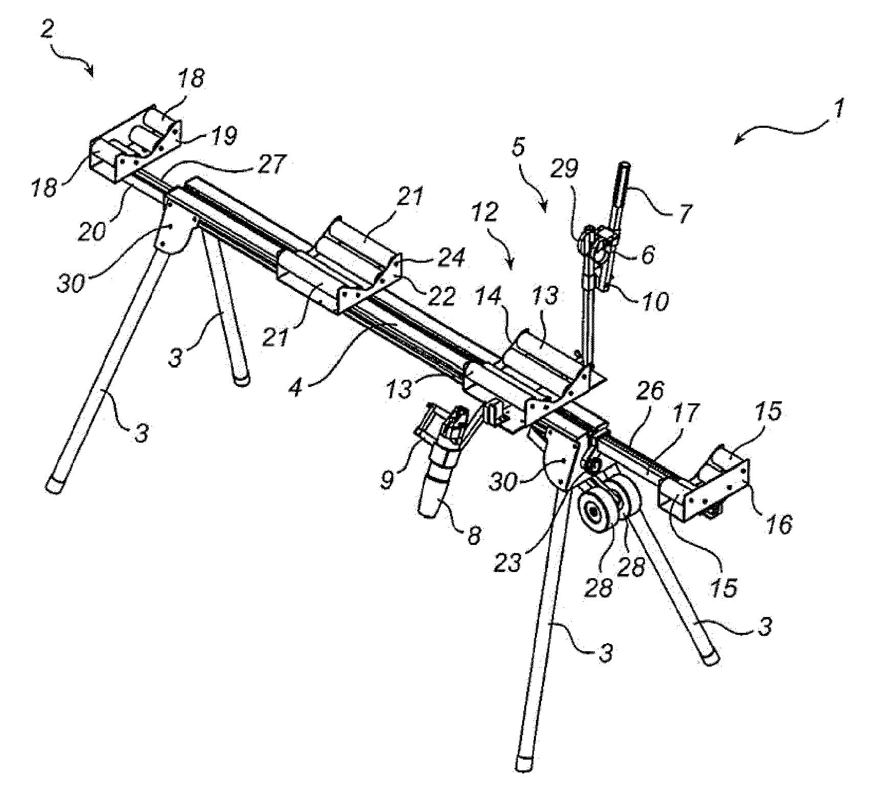
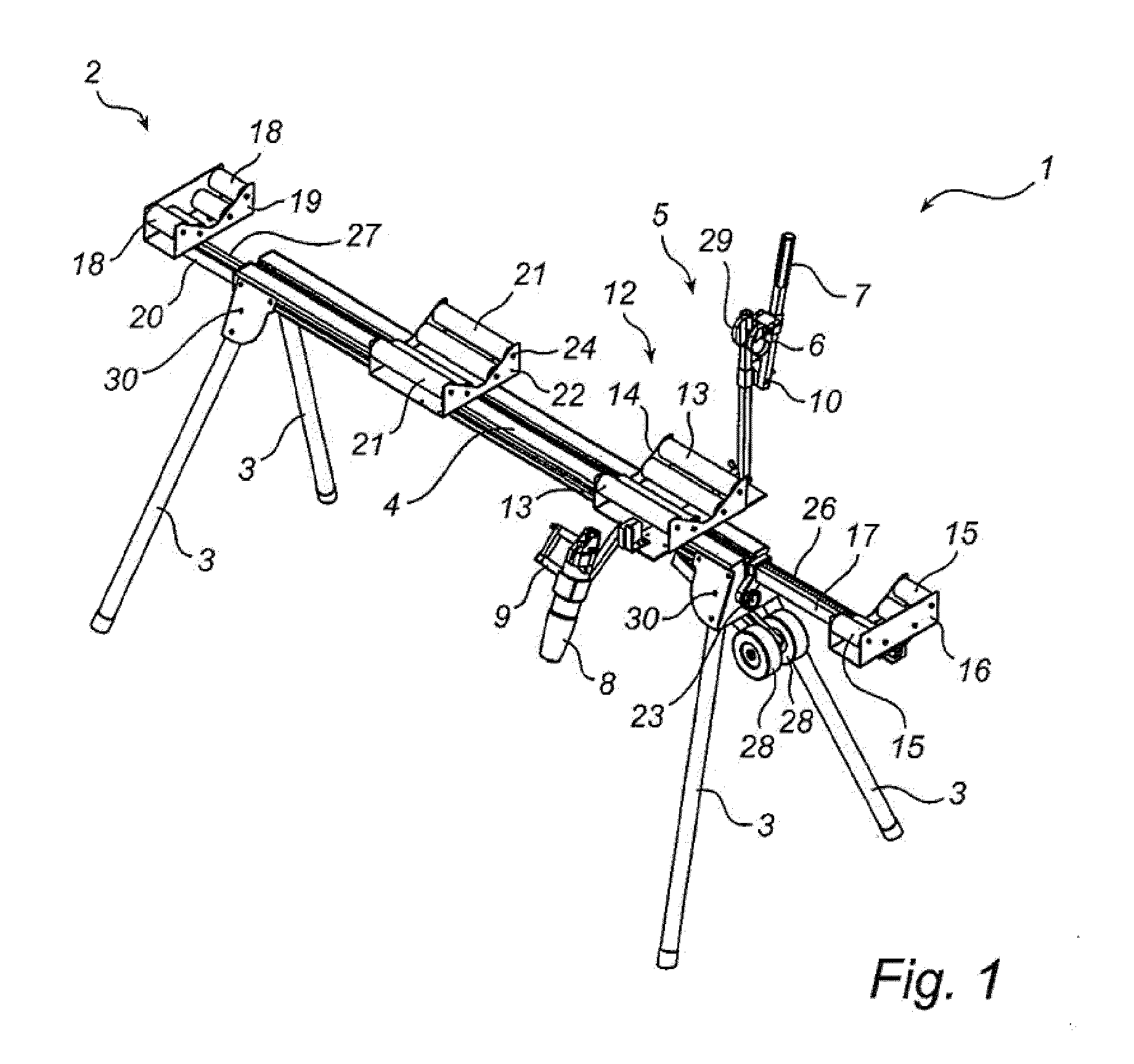
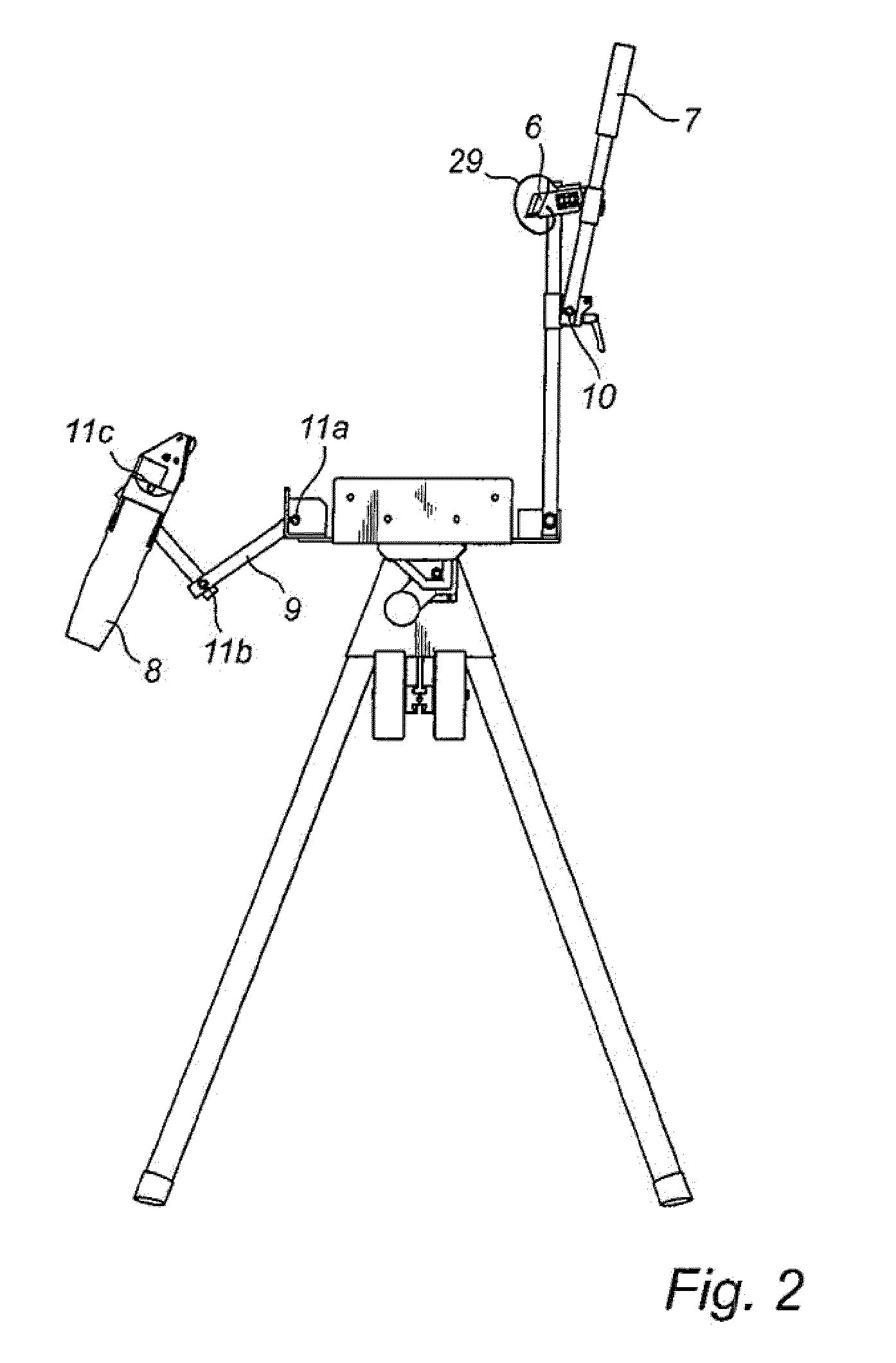
[0035]The work bench 1 shown in FIG. 1 is specifically designed for cutting tubes for ventilation duct systems, in particular helically wound lock seam tubes. The work bench 1 has a support structure 2 in the form of four foldable legs 3 and a bench surface 4. On the support structure 2 a tool assembly 5 is mounted. The tool assembly 5 consists of a knife edge 6 arranged on a pivotable arm 7 and power-driven plate shears 8 mounted on an articulated arm 9. The pivotable arm 7 on which the knife edge 6 is mounted has one pivot point 10. The articulated arm 9 on which the plate shears 8 are mounted has three pivot points 11a, 11b, 11c, as can be seen more clearly in FIG. 2.

[0036]The work bench 1 also has a holder assembly 12 for holding the tube to be cut. The holder assembly 12 is made up of a number of sets of rollers arranged in carriers. A first set of four rollers 13 is arranged in a first carrier 14 next to the tool assembly 5. The position of the first carrier 14 is fixed in rel...


PUM

PropertyMeasurementUnit
Lengthaaaaaaaaaa
Dimensionaaaaaaaaaa

Abstract

A work bench for cutting a tube comprises a support structure (2) for supporting the tube, a holder assembly (12) for holding the tube and a tool assembly (5) for cutting the tube (34). The tool assembly (5) comprises a cutting tool (8) which is restrained to move only in a plane perpendicular to a longitudinal direction of the tube (34), and that the holder assembly (12) comprises an abutment (16, 19) for an end of the tube (34). The abutment is movable in relation to the cutting tool (8) for setting a desired length of the tube (34) to be cut, and fixable to fix the position of the end of the tube (34) in relation to the cutting tool (8). A method for cutting a tube is also disclosed.

Description

TECHNICAL FIELD OF THE INVENTION[0001]The present invention relates to a work bench for cutting a tube, comprising a support structure for supporting the tube, a holder assembly for holding the tube and a tool assembly for cutting the tube. The present invention also relates to a method for cutting a tube using a work bench provided with a cutting tool arranged on an articulated arm.BACKGROUND ART[0002]When assembling ventilation systems it is very often necessary to cut the tubes into the desired length. This cutting is usually done with the tube placed on the floor. The fitter measures up the desired length on the tube with a carpenter's rule and makes a few marks along the circumference of the tube with a pencil. The fitter then uses a knife to hammer a hole into the tube at one of the marks. A drilling machine may also be used for making the hole, but the drilling machine is normally also used as a screw driver when assembling the tubes, and therefore it is necessary to frequent...

Claims


Application Information

Patent Timeline
IPC IPC(8): B26D3/16B25H1/04
CPCB23D21/00B23D29/005B25H1/06Y10T83/0596Y10T83/889Y10T83/76Y10T83/7647
Inventor BERG, OLAEINARSSON, BERNDT
Owner LINDAB
Learn More