

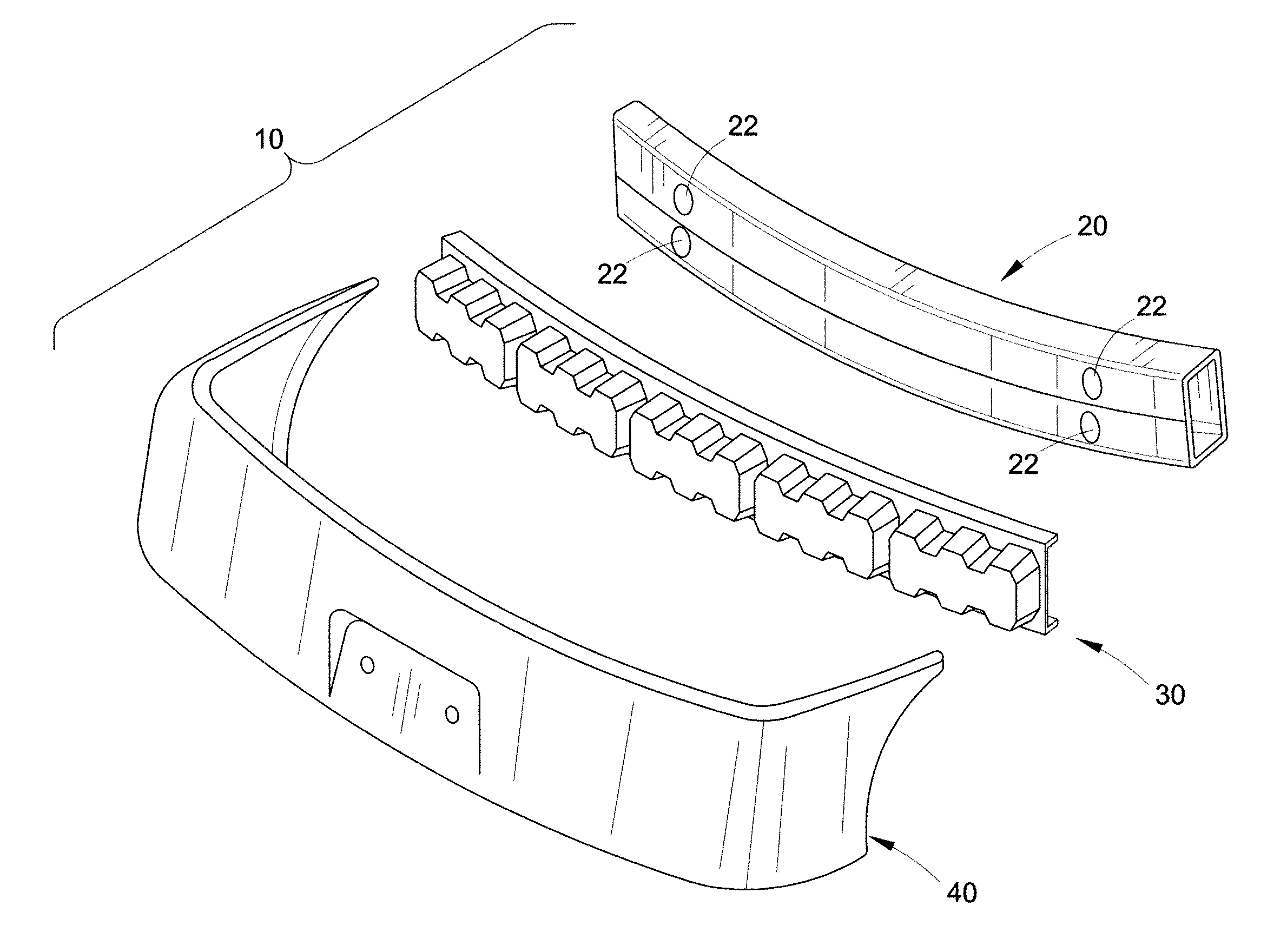
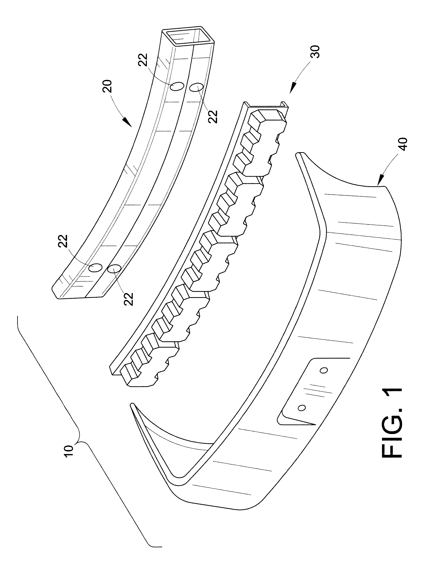
Vehicle bumper system with energy absorber
a bumper system and energy absorption technology, applied in the direction of bumpers, vehicle components, pedestrian/occupant safety arrangements, etc., can solve the problems of high displacement, achieve the effects of small volume, high efficiency, and fast loading
- Summary
- Abstract
- Description
- Claims
- Application Information
AI Technical Summary
Benefits of technology
Problems solved by technology
Method used
Image

Examples
example 1
[0059]Three different energy absorbers were modeled on a computer and tested using finite element analysis.
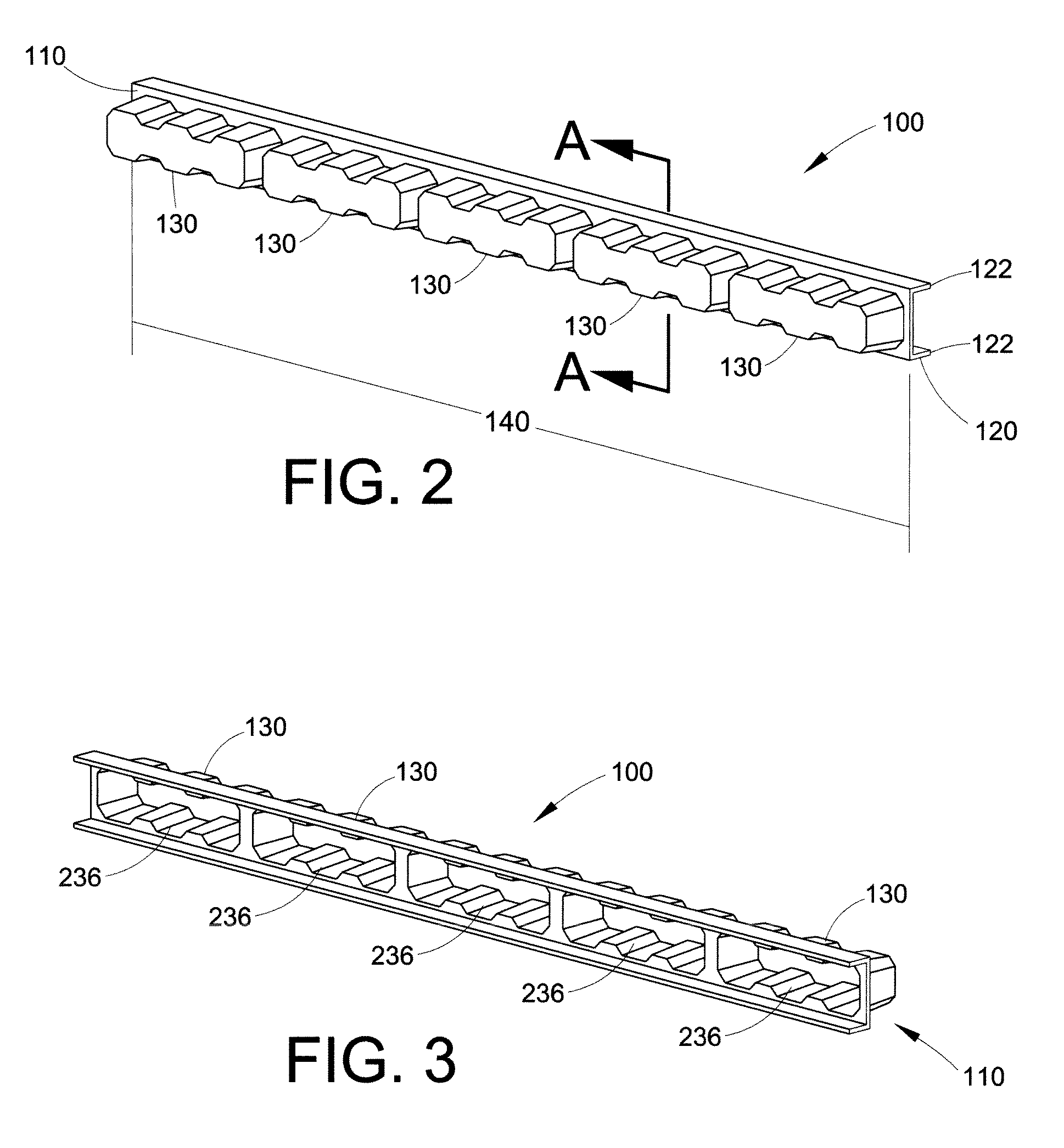
[0060]Comparative Example C1 used crush lobes with properties similar to those of injection-molded XENOY® resins. Examples E1 and E2 used crush lobes with properties similar to those of thermoformed HMD XENOY® resins. The energy absorbers each had five crush lobes separated by 60 mm. Each crush lobe was 187 mm long, 52 mm wide at the base (i.e. near the frame), and 36 mm wide at the outer surface (i.e. on the outer wall), and 50 mm deep.
[0061]The crush lobes of C1 had a constant lobe wall thickness of 2.9 mm. The total mass of each crush lobe was about 134 grams.
[0062]The crush lobes of E1 were modeled with three zones. This was done for computer-aided engineering (CAE) purposes and simplified both the modeling and analytical processes. The lobe wall thickness in the zone near the base of the crush lobe was 2.4 mm; the lobe wall thickness in the intermediate zone was 2.7 mm; an...
example 2
[0066]An energy absorber having one crush lobe was modeled and tested using a pedestrian leg form, a test that simulates hitting a pedestrian in the leg. The crush lobe had a depth of 67 mm and five thickness zones. Again, this simplified the modeling. Zone 1 was closest to the outer wall and zone 5 was closest to the frame. Zone 1 had a wall thickness of 1 mm; zone 2 had a wall thickness of 0.9125 mm; zone 3 had a wall thickness of 0.825 mm; zone 4 had a wall thickness of 0.7375 mm; and zone 5 had a wall thickness of 0.65 mm. The modeled crush lobe had a weight of about 56 grams.
[0067]The results of the crush lobe model were then compared to test results for an actual crush lobe. The actual crush lobe had a depth of 67 mm and a constantly varying thickness. The results are shown in Table 2.
TABLE 2Acceleration (g)Rotation (°)Shear (mm)Model136.913.22.6Actual13612.93.1
[0068]An excellent correlation was observed in the results for the computer modeled energy absorber and the actual en...
PUM
 Abstract
Description
Claims
Application Information