
GMR biosensor with aligned magnetic field

Active Publication Date: 2010-05-06
HEADWAY TECH INC
View PDF9 Cites 15 Cited by
  • Summary
  • Abstract
  • Description
  • Claims
  • Application Information

AI Technical Summary

Benefits of technology

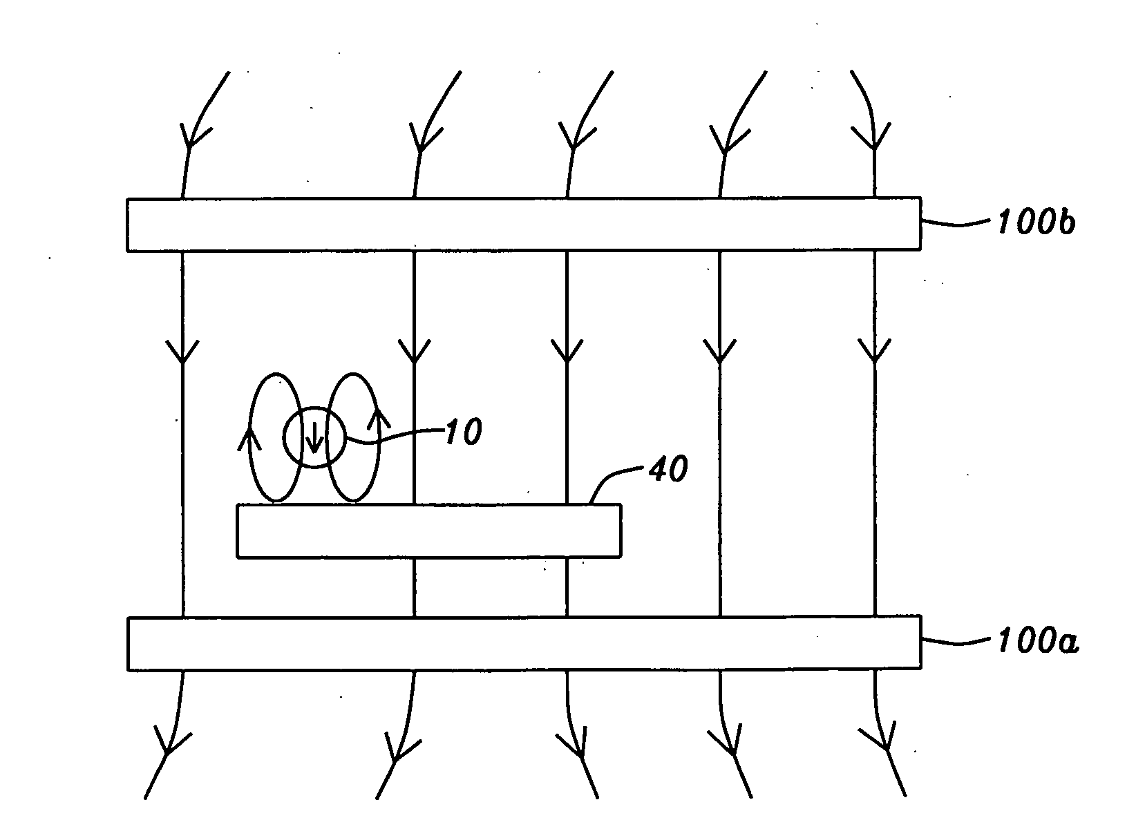
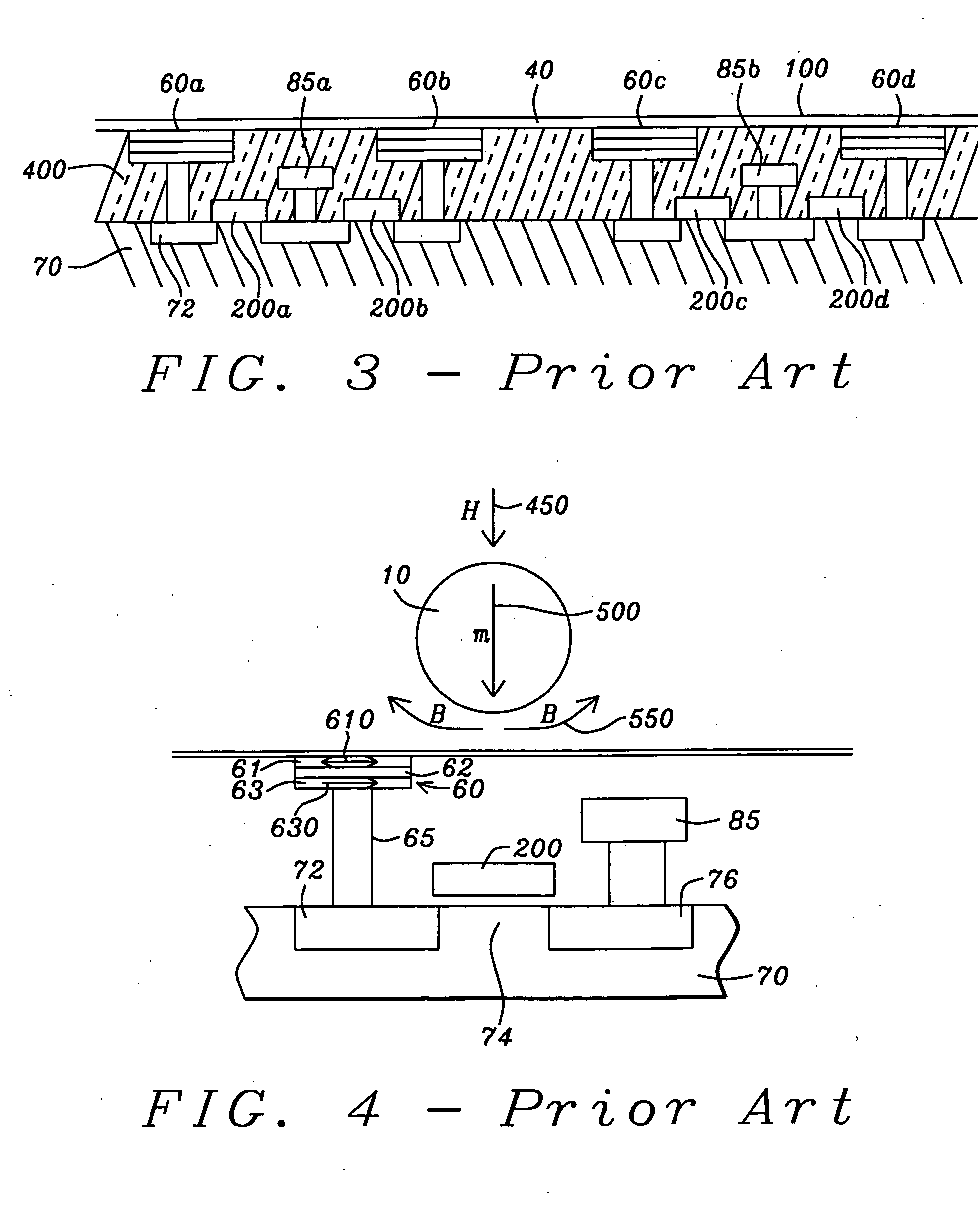
[0017]In achieving the above stated objects, the present invention addresses the fact that for an applied magnetic field, H, to be perpendicular to the substrate (i.e., to have no in-plane component), as shown by the arrow (450) in FIG. 4, it would have to be perpendicular globally, that is, over the entire region beneath which sensors are positioned. Producing and maintaining such a globally perpendicular field would be extremely difficult, because such magnetic fields, be they produced by permanent magnets or electromagnets, will naturally diverge. Thus, to avoid the effects of field line divergence in the region of the sensor array, the source of the field would have to be significantly larger than the size of the array. Such a source would be both expensive to fabricate and highly consumptive of power. The present invention will, therefore, address the problem of maintaining a perpendicular magnetic field by a process that globally self-aligns the applied magnetic field so as to maintain perpendicularity with the sensor substrate while doing so in a simple manner that does not require changing the way in which the field itself is produced.

Problems solved by technology

The technological issue, then, is to provide an effective method of detecting these small magnetic labels, since their detection is tantamount to detection of the target molecules.
If, however, the applied magnetic field, H, were not perpendicular, its in-plane component could significantly perturb the effects of B, and thereby adversely affect the accuracy of the sensor.
The presence of an in-plane component can also adversely affect the signal-to-noise ratio of such a sensor, as is noted by Kahlman et al.

Method used


Image

  • GMR biosensor with aligned magnetic field
  • GMR biosensor with aligned magnetic field
  • GMR biosensor with aligned magnetic field

Examples


Embodiment Construction

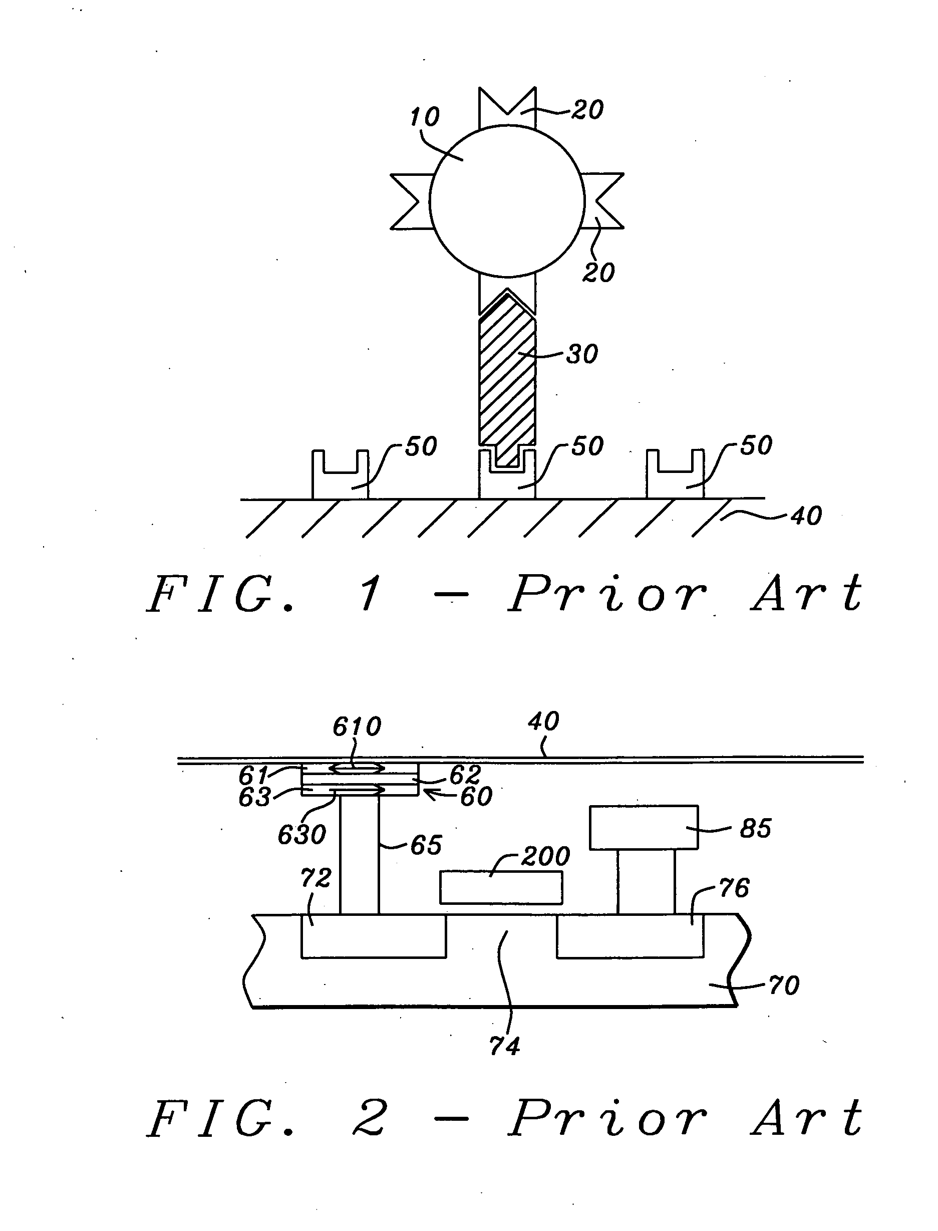
[0033]Although any planar sensor whose electrical impedance is affected by an external impinging magnetic field that has an in-plane component can be used to meet the objects of this invention, a preferred embodiment of the present invention uses a planar laminated GMR or TMR based sensor (i.e., an array of GMR or TMR cell elements formed on a planar substrate). This sensor will be used for detecting the presence of small magnetized particles (also called magnetic labels), typically bonded to chemical molecules and thereby affixed to the sensor surface. The GMR or TMR based planar sensor, by virtue of a proximate, parallel and at least co-extensive layer of soft (low coercivity, high permeability) magnetic material, called a keeper layer, formed closely adjacent to the array, for example, upon it or beneath it or both, is then not adversely affected by an in-plane component of an external static magnetic field that is used to induce a magnetic moment in the magnetic particles. The l...


PUM


Abstract

A planar array of GMR or TMR sensor elements with planar free and pinned layers is used as the basis of a sensor for detecting the presence of small magnetized particles. In particular, the sensor is used for detecting the presence of magnetized particles bonded to biological molecules that are themselves bonded to a substrate. The magnetized particles on the molecules are detected by the sensors as a result of the interaction between the stray fields of the particles and the magnetic configuration of the sensors. By forming a co-planar layer of soft magnetic material over the sensor or its array, the external field used to magnetize the particles is self-aligned perpendicularly to the sensor plane whereby it does not interfere with the stray fields of the particles.

Description

BACKGROUND OF THE INVENTION[0001]1. Field of the Invention[0002]This invention relates to a magnetic sensor for the detection of small particles magnetized by an external magnetic field, particularly to such a sensor that utilizes an external field applied in a direction perpendicular to the sensor plane.[0003]2. Description of the Related Art[0004]Magnetic sensors have been shown as capable of detecting the presence of specific chemical and biological molecules when such molecules are a part of a fluid mixture that includes many other types of molecules. The method underlying such magnetic detection of molecules requires that labels, comprising small magnetic (or magnetizable) particles, be attached to the specific molecules in the mixture that are of interest. The magnetic particles used as such labels may have ferromagnetic, ferrimagnetic, paramagnetic or superparamagnetic properties. Particles with ferromagnetic or ferrimagnetic characteristics have intrinsic magnetic moments, w...

Claims


Application Information

Patent Timeline
IPC IPC(8): G01R33/00
CPCG01R33/1269
Inventor VOEGELI, OTTO
Owner HEADWAY TECH INC
Learn More