
Large depth-of-field imaging system and iris recogniton system

a technology of iris recognition and imaging system, which is applied in the field of imaging systems, can solve the problems of reducing the light-gathering ability requiring large depth of field of the optical system, and requiring large fov, and achieves the effect of enhancing the modulation transfer function (mtf)

Inactive Publication Date: 2010-05-06
GLOBAL BIONIC OPTICS PTY LTD
View PDF15 Cites 91 Cited by
  • Summary
  • Abstract
  • Description
  • Claims
  • Application Information

AI Technical Summary

Benefits of technology

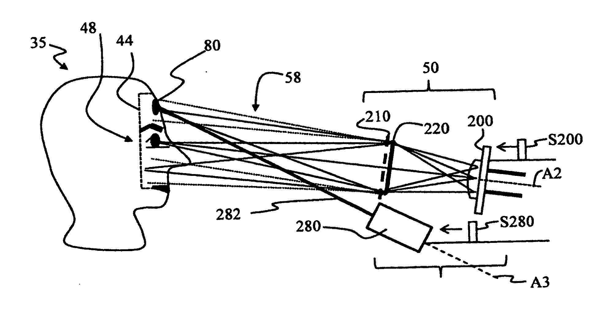
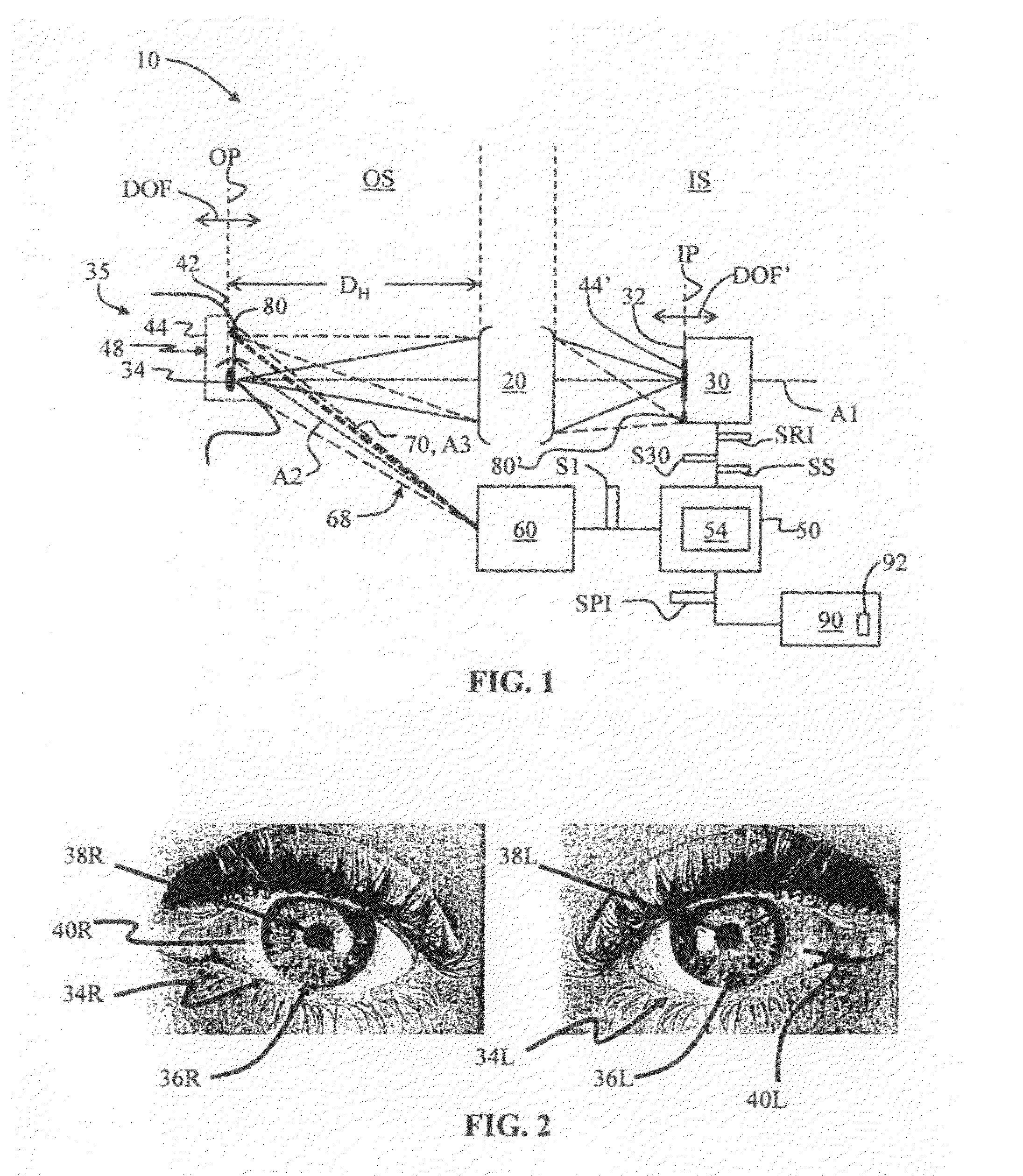
[0011]An aspect of the invention is an iris-recognition (I-R) system for capturing images of one or both irises of a person over a large depth of field (DOF). The I-R system includes an illumination system adapted to i) illuminate at an imaging wavelength λIM a facial region of the person, wherein the facial region includes one or both eyes and at least a forehead portion of the person, and ii) to form a spot on the forehead portion. The I-R system also includes an optical system having an object plane within the large depth of field DOF, an image plane within a correspondingly large depth of focus DOF′. An image sensor is arranged at the image plane. The optical system is provided with an amount of spherical aberration (SA) at an imaging wavelength λIM such that the depth of field DOF incre...

Problems solved by technology

A major shortcoming of many iris recognition systems is that the optical system requirements of large depth of field, sufficiently large FOV, and high-resolution are somewhat contradictory.
A relatively high NA also decreases the light-gathering ability of the optical system so that longer exposure is required to capture an iris image.

Method used


Image

  • Large depth-of-field imaging system and iris recogniton system
  • Large depth-of-field imaging system and iris recogniton system
  • Large depth-of-field imaging system and iris recogniton system

Examples


Embodiment Construction

[0046]Reference is now made in detail to the present preferred embodiments of the invention, examples of which are illustrated in the accompanying drawings. Whenever possible, like or similar reference numerals are used throughout the drawings to refer to like or similar parts. Various modifications and alterations may be made to the following examples within the scope of the present invention, and aspects of the different examples may be mixed in different ways to achieve yet further examples. Accordingly, the true scope of the invention is to be understood from the entirety of the present disclosure, in view of but not limited to the embodiments described herein.

[0047]The present invention is directed to enhanced DOF imaging systems. A generalized iris-recognition system based on the enhanced DOF imaging system of the present invention is first discussed, followed by more detailed descriptions of the various components that make up the I-R system, along with the corresponding meth...


PUM


Abstract

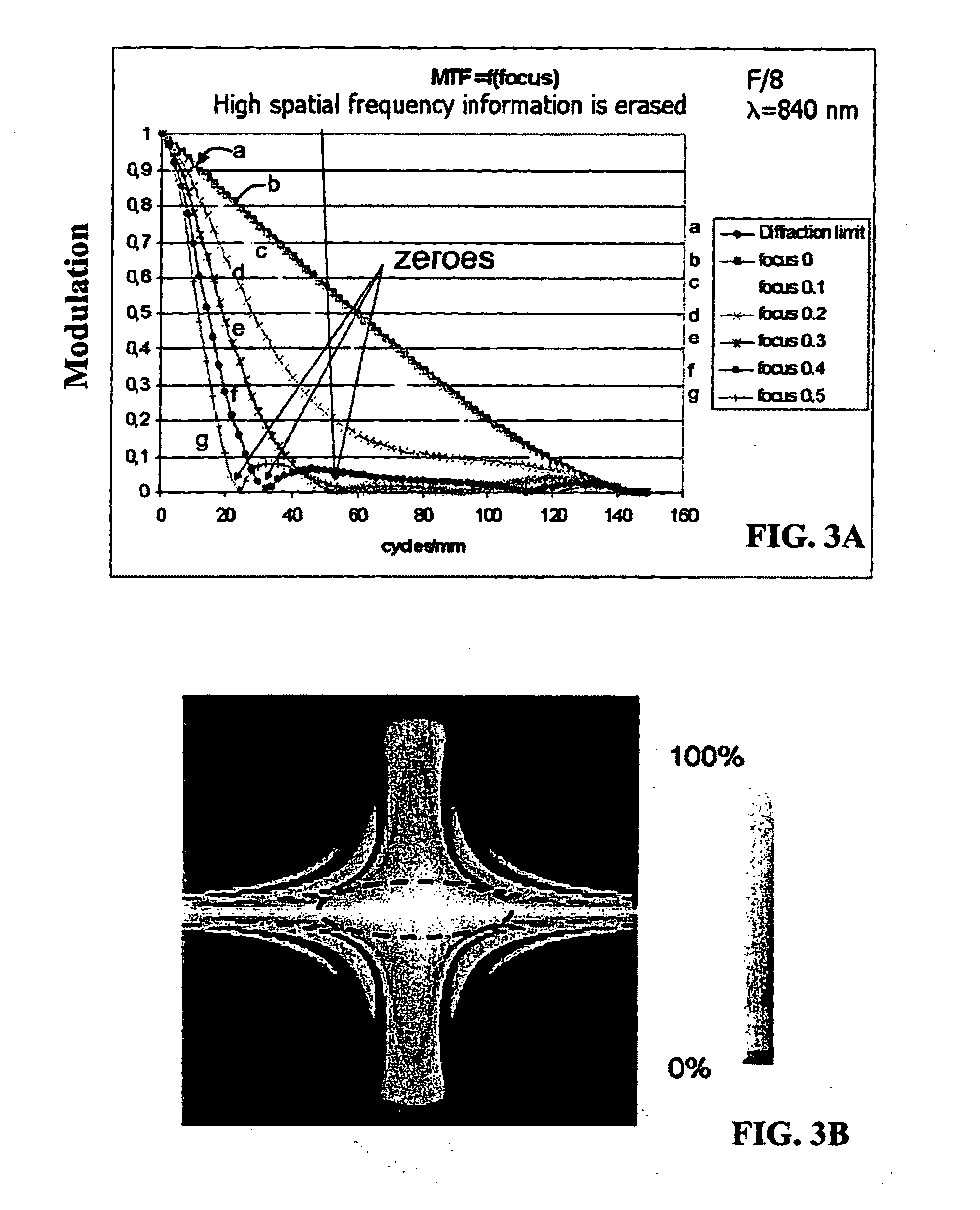
(A2) An extended depth of field (DOF) imaging system (10) is disclosed that has a corresponding extended depth of focus (DOF′) by virtue of its optical system (20) having a select amount of spherical aberration. The imaging system has an image processing unit (54) adapted to process the raw images and perform contrast enhancement to form processed images. The image processing includes restoring the defocused modulation transfer functions (MTFs) using a gain function (G) and the amount of defocus. The imaging system can include an illumination system (60) that illuminates the object being imaged to establish a distance (DH) between the optical system and the object, where distance DH is used in the restoring of the MTF. An iris-recognition (I-R) system based on the enhanced DOF imaging system is also disclosed.; Optical system embodiments for use in the DOF imaging system that can provide select amounts of spherical aberration—and thus select increases in DOF—without increasing the adverse impact of other aberrations on image formation are also disclosed.

Description

CLAIM OF PRIORITY[0001]This application claims the benefit of priority of European Patent Application Serial No. EP 07300936.7, filed on Apr. 6, 2007, which patent application is incorporated by reference herein.BACKGROUND ART[0002]1. Field of the Invention[0003]The present invention relates generally to imaging systems, and particularly large depth-of-field imaging systems, and more particularly to large depth-of-field iris recognition systems.[0004]2. Technical Background[0005]Humans have a number of unique physical characteristics, such as fingerprints, iris patterns, and voices, whose measurement allows for distinguishing one person from another. The science of measuring such characteristics is known as “biometrics.”[0006]The measurement of a person's iris pattern to perform biometric identification (“authentication”) is called “iris recognition.” Iris recognition involves taking an image of a person's iris and then using pattern recognition techniques to create the equivalent o...

Claims


Application Information

Patent Timeline
IPC IPC(8): G06K9/40G06T7/00H04N5/225
CPCA61B5/1171A61B3/14A61B5/117G06K9/00604G02B27/0025G02B27/0075G02B13/20G06V40/19
Inventor MATHIEU, GILLES
Owner GLOBAL BIONIC OPTICS PTY LTD
Learn More