Suspension board with circuit

a suspension board and circuit technology, applied in the direction of maintaining head carrier alignment, integrated arm assemblies, instruments, etc., can solve the disadvantageous limitation of layout design, the inability to compactly mount the suspension board with circuit on the hard disk drive, and the short circuit between, so as to enhance the design flexibility of the layout and enhance the flexibility of the layout of the slider and the light emitting device.

Inactive Publication Date: 2010-05-06
NITTO DENKO CORP
View PDF21 Cites 24 Cited by
  • Summary
  • Abstract
  • Description
  • Claims
  • Application Information

AI Technical Summary

Benefits of technology

[0027]Therefore, the magnetic head and the light emitting device are electrically connected to the first terminal and the second terminal, respectively, bot...

Problems solved by technology

Therefore, these two terminal portions are inevitably arranged densely thereon, thus easily causing a short circuit between them.
However, the wider space causes a problem that the suspension board with circuit cannot ...

Method used


Image

  • Suspension board with circuit
  • Suspension board with circuit
  • Suspension board with circuit

Examples


Embodiment Construction

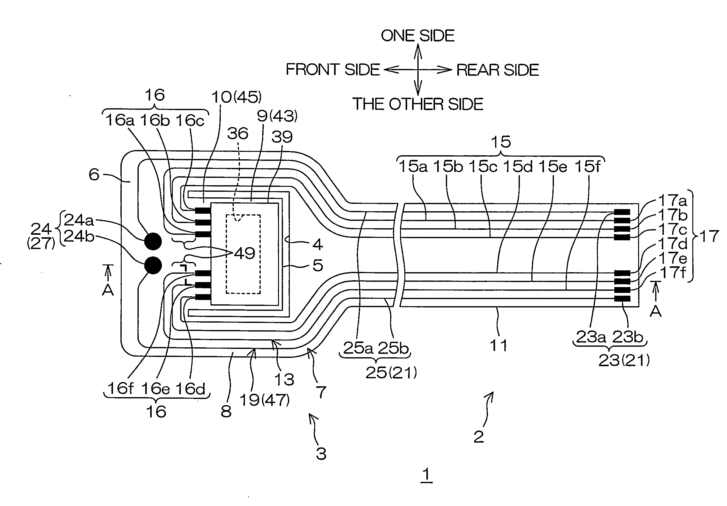
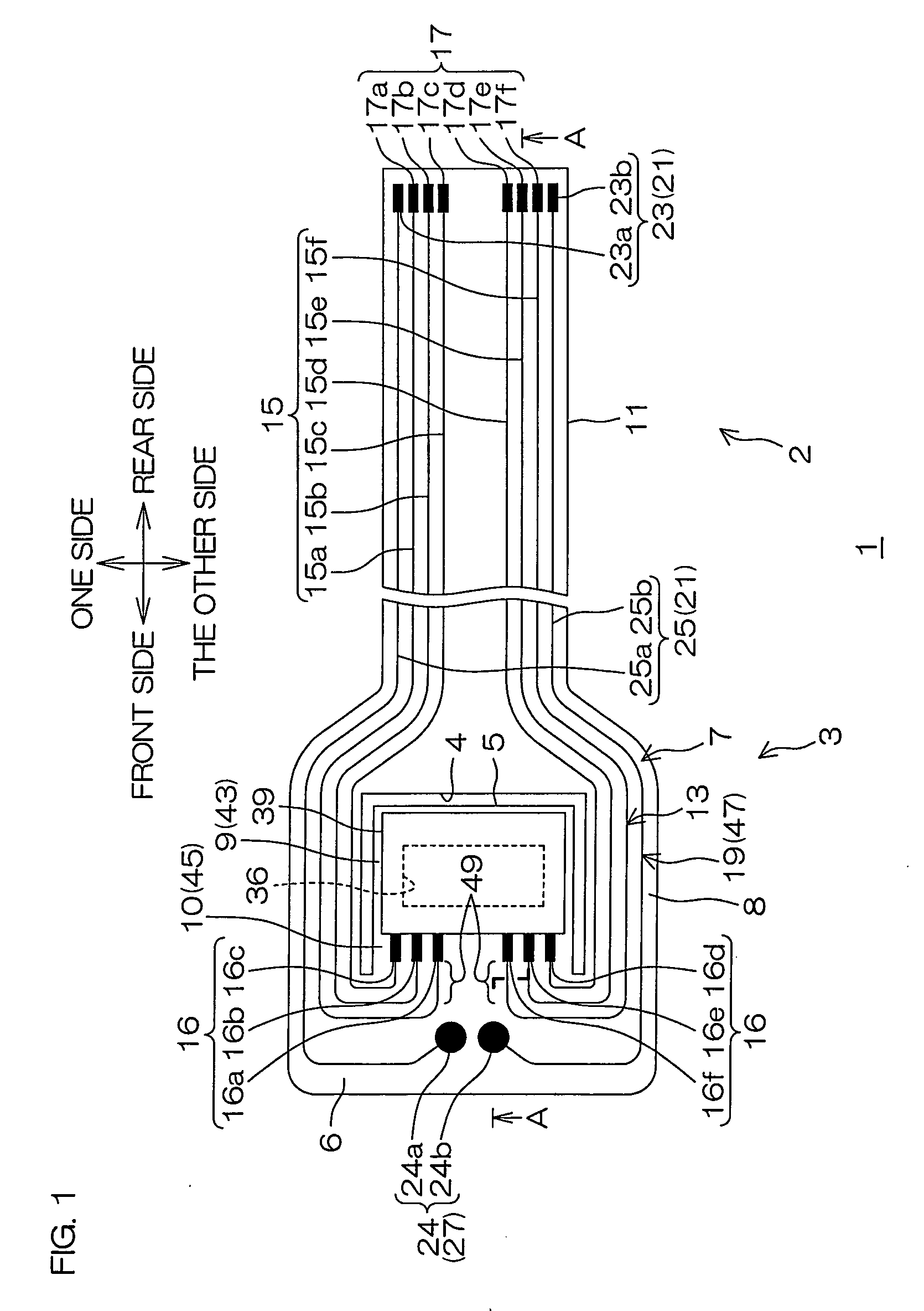
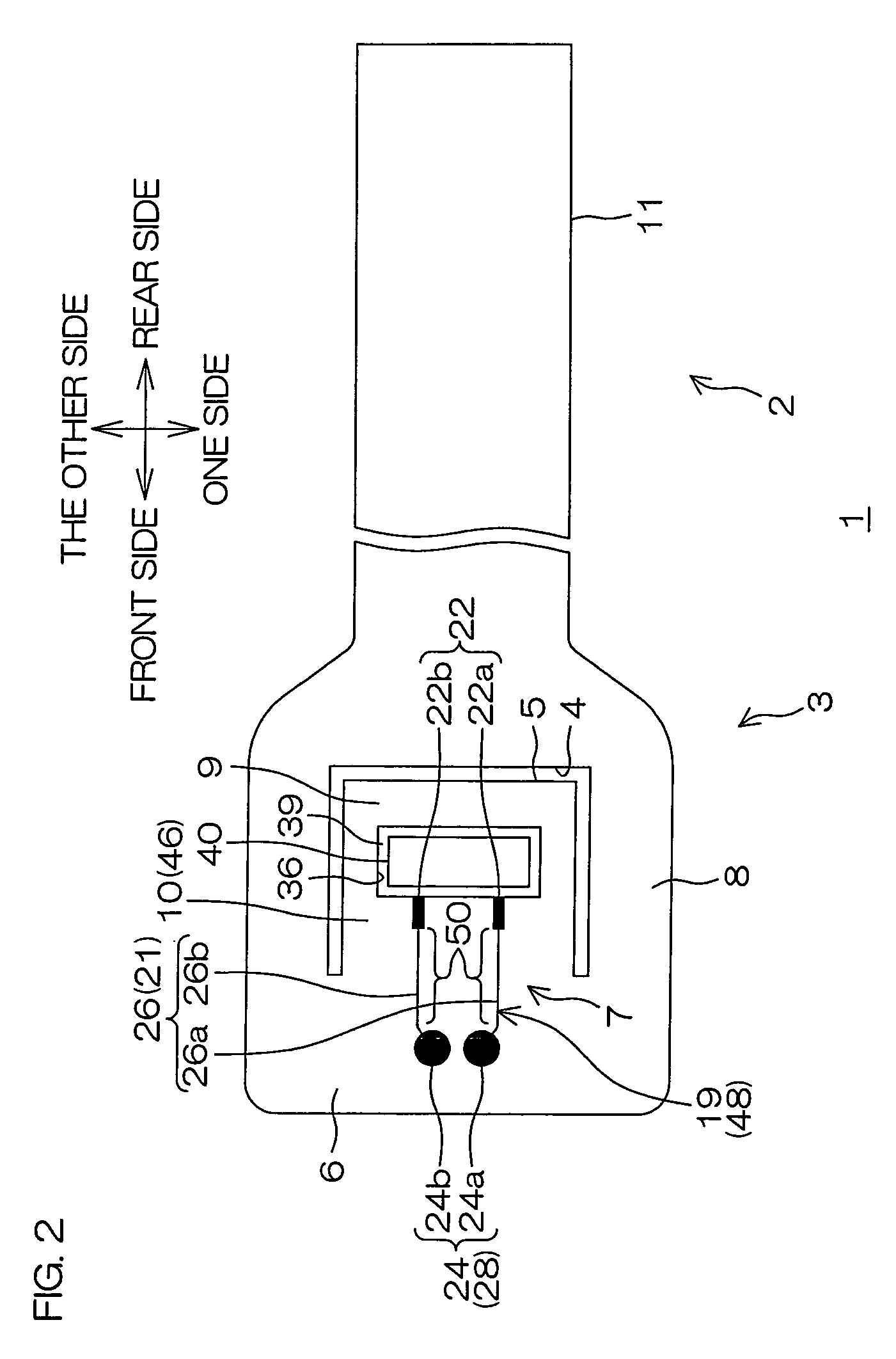
[0113]FIG. 1 is a plan view illustrating a suspension board with circuit of an embodiment according to the present invention; FIG. 2 is a bottom view of the suspension board with circuit shown in FIG. 1; FIG. 3 is a sectional view of the suspension board with circuit taken along the line A-A shown in FIG. 1; FIG. 4 is an enlarged sectional view of a conductive portion shown in FIG. 3; and FIGS. 5 and 6 is process diagrams explaining a method for producing the suspension board with circuit shown in FIG. 3.

[0114]To clearly illustrate a relative position of a conductive pattern 7 to be described later, a first insulating base layer 12 and a first insulating cover layer 14, both described later, are omitted in FIG. 1. In addition, to clearly illustrate a relative position of the conductive pattern 7 to be described later, a second insulating base layer 18 and a second insulating cover layer 20, both described later, are omitted in FIG. 2.

[0115]In FIGS. 1 to 3, the suspension board with ...


PUM


Abstract

A suspension board with circuit includes a conductive pattern, including a slider arranged on a surface side of the suspension board with circuit and mounted with a magnetic head, the magnetic head being electrically connected with the conductive pattern; and a light emitting device arranged on the back surface side of the suspension board with circuit and electrically connected with the conductive pattern, in which the conductive pattern includes a first terminal provided on a surface of the suspension board with circuit and electrically connected with the magnetic head; and a second terminal provided on the back surface of the suspension board with circuit and electrically connected with the light emitting device.

Description

CROSS REFERENCE TO RELATED APPLICATIONS[0001]This patent application claims the benefit of U.S. Provisional Application No. 61 / 193,272, filed on Nov. 12, 2008, and claims priority from Japanese Patent Application No. 2008-282166, filed on Oct. 31, 2008, the contents of which are herein incorporated by reference in their entirety.BACKGROUND OF THE INVENTION[0002]1. Field of the Invention[0003]The present invention relates to a suspension board with circuit. More particularly, the present invention relates to a suspension board with circuit used in a hard disk drive which adopts an optical assist system.[0004]2. Description of Related Art[0005]In recent years, there has been known that a suspension board with circuit is used in a hard disk drive which adopts an optical assist system. The optical assist system is a recording system capable of recording information with a magnetic head in a state where a magnetic disk is heated under light irradiation from a light emitting device during...

Claims


Application Information

Patent Timeline
IPC IPC(8): G11B5/60
CPCG11B5/4853H05K1/056H05K1/182H05K3/06H05K3/445H05K2201/0394H05K2201/09509H05K2201/096H05K2201/0969H05K2201/10106H05K2201/10537H05K2201/10545H05K2201/10727H05K2203/0323H05K2203/0361G11B13/04G11B5/4833G11B5/484G11B2005/0021
Inventor OHSAWA, TETSUYAABE, HAYATOYOSHIDA, YOSHINARINAITO, TOSHIKI
Owner NITTO DENKO CORP
Why Eureka
Try Eureka