Spin torque oscillator, magnetic recording head, magnetic head assembly and magnetic recording apparatus

a technology of spin torque oscillator and magnetic recording head, which is applied in the direction of magnetic recording, data recording, instruments, etc., can solve the problems of slowing down temporarily the speed of the increase in recording density, not being able to achieve such a high recording density, and being difficult to efficiently apply the high frequency magnetic field to the medium

Active Publication Date: 2010-05-06
KK TOSHIBA
View PDF98 Cites 51 Cited by
  • Summary
  • Abstract
  • Description
  • Claims
  • Application Information

AI Technical Summary

Problems solved by technology

However, since the problem of heat fluctuation of a magnetic recording medium became conspicuous in the early 2000s, the speed of the increase in recording density slowed down temporarily.
However, it will not be easy to attain such a high recording density even employing the perpendicular magnetic recording, because the problems of heat fluctuation will still become conspicuous.
However, the method employs a coil to generate the high frequency magnetic field, making it difficult to efficiently apply the high frequency magnetic field to the medium.
However, all the items give rise to an increase in the driving current.

Method used


Image

  • Spin torque oscillator, magnetic recording head, magnetic head assembly and magnetic recording apparatus
  • Spin torque oscillator, magnetic recording head, magnetic head assembly and magnetic recording apparatus
  • Spin torque oscillator, magnetic recording head, magnetic head assembly and magnetic recording apparatus

Examples


first embodiment

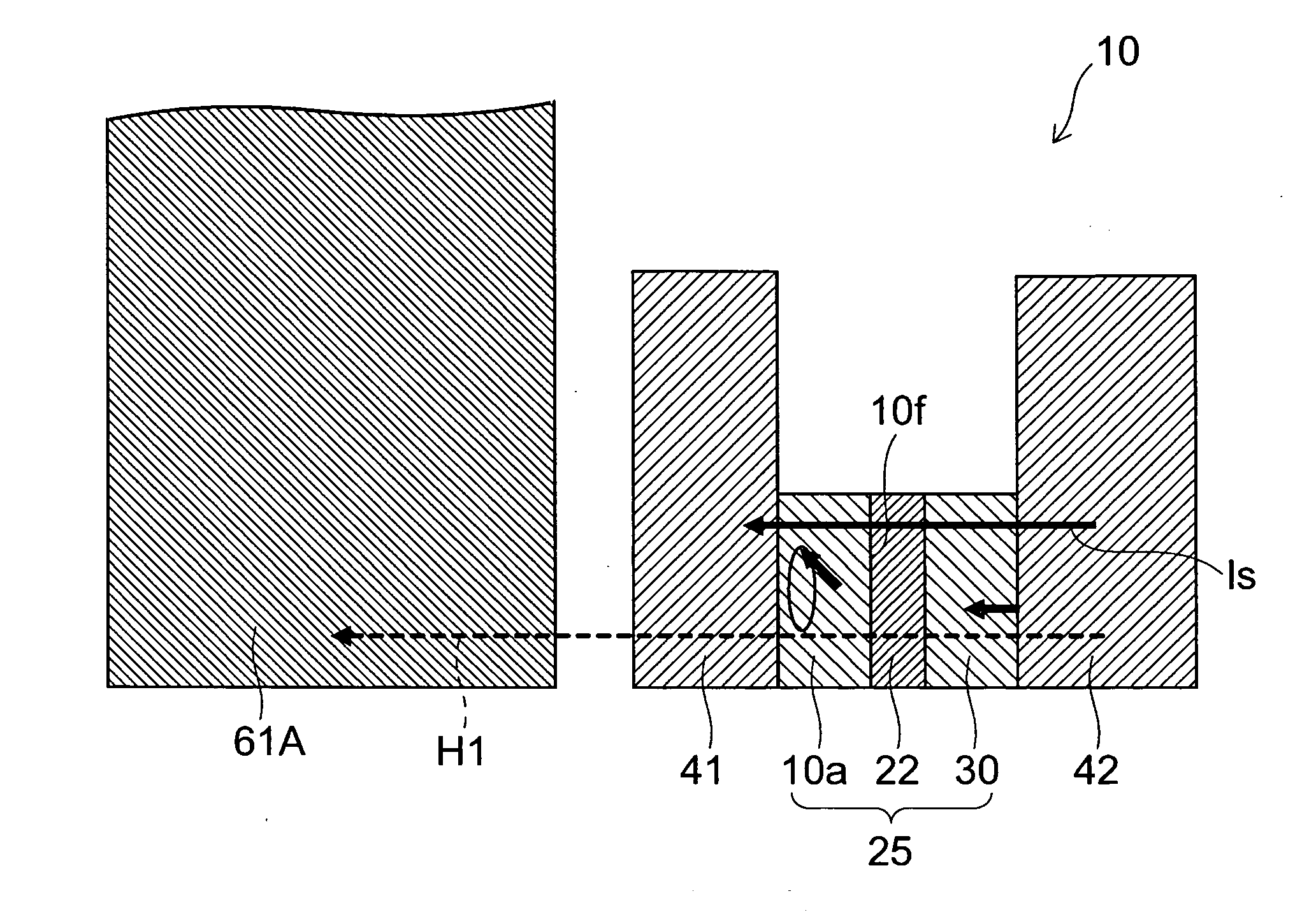
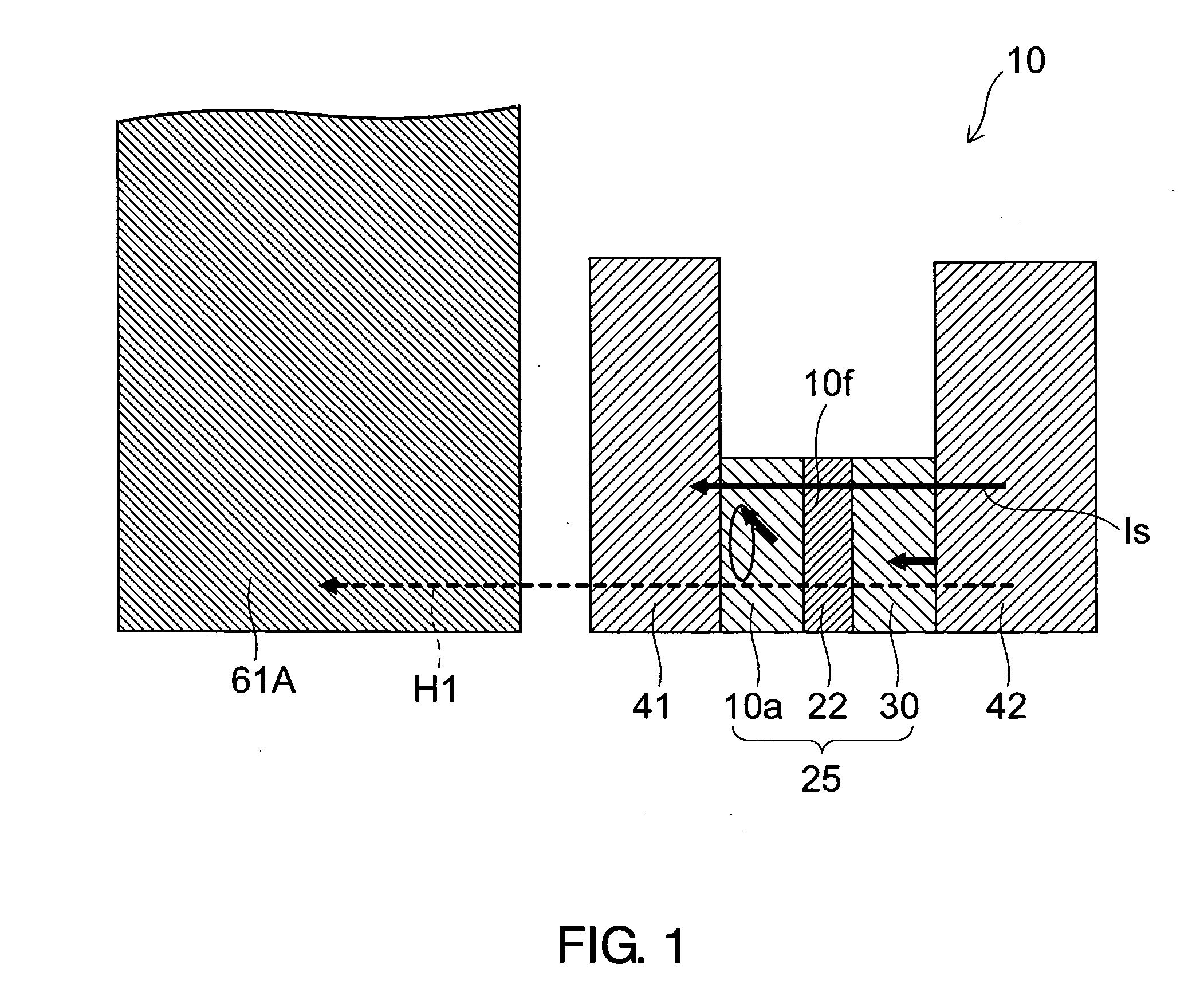
[0030]FIG. 1 is a sectional view illustrating a configuration of a spin torque oscillator according to a first embodiment of the present invention. As shown in FIG. 1, the spin torque oscillator 10 according to the first embodiment of the invention has a laminated structure 25 which is provided with an oscillation layer (amorphous soft magnetic layer) 10a, a spin injection layer (hard magnetic layer) 30, and a nonmagnetic layer 22 disposed between the oscillation layer 10a and the spin injection layer 30.

[0031]The oscillation layer 10a is a magnetic film including a magnetic material with a body-centered cubic (bcc) structure, and orients so that a plane parallel to a {110} plane of the bcc structure is a principal plane 10f. The “principal plane” is defined as a plane parallel to a lamination plane of the laminated structure 25. The {110} plane includes a crystallographically equivalent planes such as a (110) plane, a (101) plane, a (011) plane, etc. Below, it is assumed that the {...

first example

[0064]A spin torque oscillator 101 (not shown in the figure) according to the first example of the invention is a spin torque oscillator made employing a bcc (110)-oriented Fe50Co50 film for the oscillation layer 10a. That is, the followings were employed:

the bcc (110)-oriented Fe50Co50 film with a thickness of 5 nm, which was formed on an 10 nm-thick laminated underlayer formed of a Ta film and a Ru film, was employed for the oscillation layer 10a;

a 20-nm thick Cu film was employed for the intermediate layer 22; and

a CoPt film was employed for the spin injection layer 30.

[0065]A spin torque oscillator 101c (not shown) was made employing a bcc (100)-oriented Fe50Co50 film for the oscillation layer 10a.

That is, the followings were employed:

a 5-nm thick Fe50Co50 film, which was formed on a 10 nm-thick MgO (100) layer, was employed for the oscillation layer 10a;

a 20-nm thick Cu film was employed for the intermediate layer 22; and

a CoPt film was employed for the spin injection layer ...

second embodiment

[0069]A spin torque oscillator 12 (not shown) according to a second embodiment of the invention employs a bcc alloy including Fe with at least one of Al, Si, Ga, Ge, P, Sn, and Cu added by a composition ratio of 5 atomic %. Except this, the spin torque oscillator 12 is the same as the spin torque oscillator 10. Thus, the explanation is omitted thereon.

[0070]The material with the above elements added is employed for the oscillation layer 10a of the spin torque oscillator 12 according to this embodiment to change the electronic state of the metal magnetic layer, thereby allowing it to reduce the dumping factor α.

[0071]When the concentration of the added element is less than 5 atomic %, the influence of the added element on the electronic state becomes small, thereby significantly lowering the effect for reducing the driving current J. When the concentration exceeds 50 atomic %, the magnetism of the oscillation layer 10a becomes unstable, thereby requiring that the concentration is bel...


PUM

PropertyMeasurementUnit
thicknessaaaaaaaaaa
distanceaaaaaaaaaa
sizeaaaaaaaaaa

Abstract

A spin torque oscillator includes a first magnetic layer, a second magnetic layer and a first nonmagnetic layer. The first magnetic layer includes a magnetic film of a magnetic material with a body-centered cubic (bcc) structure and an oriented {110} plane of the body-centered cubic structure, the oriented {110} plane being oriented substantially parallel to a principal plane of the magnetic film. The first nonmagnetic layer is disposed between the first magnetic layer and the second magnetic layer. In addition, a magnetic moment in the magnetic film precesses around an axis substantially parallel to the principal plane. Furthermore, a magnetic field is applied in a direction substantially perpendicular to the principal plane, and a current is passed perpendicularly to the principal plane.

Description

CROSS REFERENCE TO RELATED APPLICATION[0001]This application is based upon and claims the benefit of priority from the Japanese Patent Application No. 2008-285830, filed on Nov. 6, 2008, the entire contents of which are incorporated herein by reference.FIELD OF THE INVENTION[0002]The present invention relates to a spin torque oscillator, a magnetic recording head, a magnetic head assembly, and a magnetic recording apparatus.DESCRIPTION OF THE BACKGROUND[0003]In the 1990s, the practical application of an MR (Magneto-Resistive effect) head and a GMR (Giant Magneto-Resistive effect) head has contributed to the skyrocketing of the recording density and capacity of an HDD (Hard Disk Drive). However, since the problem of heat fluctuation of a magnetic recording medium became conspicuous in the early 2000s, the speed of the increase in recording density slowed down temporarily. Even so, a perpendicular magnetic recording was put in practical use in 2005, the perpendicular magnetic recordin...

Claims


Application Information

Patent Timeline
Patent Type & Authority Applications(United States)
IPC IPC(8): G11B5/33
CPCG11B5/02G11B5/1278G11B5/314G11B2005/0002G11B2005/0024
Inventor KOUI, KATSUHIKOSHIMIZU, MARIKOYAMADA, KENICHIRO
Owner KK TOSHIBA
Why Eureka
Try Eureka