Power factor correction circuit and driving method thereof

a technology of power factor and circuit, applied in the direction of emergency protective circuit arrangement, efficient power electronics conversion, etc., can solve the problems of time delay until the switch is substantially turned off, the current of the switch is radically increased, and the switch may be damaged

Active Publication Date: 2010-05-06
SILICON MITUS
View PDF11 Cites 72 Cited by
  • Summary
  • Abstract
  • Description
  • Claims
  • Application Information

AI Technical Summary

Benefits of technology

[0020]According to the present invention, the switch can be protected at the diode sho...

Problems solved by technology

However, a time delay occurs until the switch is substantially turned off due to circuits existing in the middle of transmission of the signal to the switch.
However, when the diode D is short-circuited, the switch current is radically increased for a short time delay because the switch current has a steep slope so that a current increase r2 is very large.
When the diode D is short-circuited, temperature of the switch is increased...

Method used


Image

  • Power factor correction circuit and driving method thereof
  • Power factor correction circuit and driving method thereof
  • Power factor correction circuit and driving method thereof

Examples


Embodiment Construction

[0033]In the following detailed description, only certain exemplary embodiments of the present invention have been shown and described, simply by way of illustration. As those skilled in the art would realize, the described embodiments may be modified in various different ways, all without departing from the spirit or scope of the present invention.

[0034]Accordingly, the drawings and description are to be regarded as illustrative in nature and not restrictive. Like reference numerals designate like elements throughout the specification.

[0035]Hereinafter, a power factor correction circuit and a diode short-circuit protection circuit thereof according to an exemplary embodiment of the present invention will be described in detail with reference to the drawings.

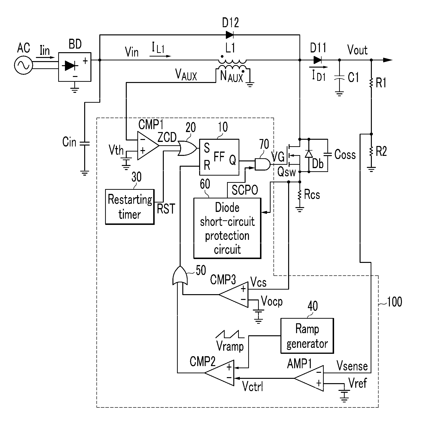
[0036]FIG. 5 shows a power factor correction circuit according to a first exemplary embodiment of the present invention.

[0037]Referring to FIG. 5, a power factor correction circuit according to the first exemplary embodiment of ...


PUM


Abstract

The present invention relates to a set protection circuit for when a diode short-circuit defect occurs in a power factor correction circuit of a critical conduction mode. In a conventional power factor correction circuit, an excessive amount of current flows to a switch if a diode is short-circuited so that the switch is damaged. In order to prevent damage to the switch, the present invention provides a method for stopping turn-on of the switch when a switch current is excessive.

Description

CROSS-REFERENCE TO RELATED APPLICATION[0001]This application claims priority to and the benefit of Korean Patent Application No. 10-2008-0108522 filed in the Korean Intellectual Property Office on Nov. 3, 2008, the entire contents of which are incorporated herein by reference.BACKGROUND OF THE INVENTION[0002](a) Field of the Invention[0003]The present invention relates to a power factor correction circuit. More particularly, it relates to a power factor correction circuit for solving a problem of a diode short-circuit occurring in a conventional power factor correction circuit, and a driving method thereof.[0004](b) Description of the Related Art[0005]A switching mode power supply (SMPS) in which a power factor correction circuit is not used generates a pulse-type input current to make a high-level harmonic current flow to an electricity transmission line. The pulse-type current increases a loss of a power transmission line and a transformer rather than contributing to power transmi...

Claims


Application Information

Patent Timeline
IPC IPC(8): H02H7/00
CPCH02M1/32H02M1/4225Y02B70/126Y02B70/10H02M1/42H02M3/155
Inventor KIM, DONG-HEEKIM, JUNG-WONKIM, DAE-JUNG
Owner SILICON MITUS
Why Eureka
Try Eureka