System and method for planning and guiding percutaneous procedures

a percutaneous procedure and guidance system technology, applied in the direction of material analysis using wave/particle radiation, instruments, nuclear engineering, etc., can solve the problems of affecting the actual position of the needle relative to the patient, requiring the patient to be moved, and the registration error between the live fluoroscopic image and the registration error,

Inactive Publication Date: 2010-05-06
SIEMENS CORP +1
View PDF9 Cites 36 Cited by
  • Summary
  • Abstract
  • Description
  • Claims
  • Application Information

AI Technical Summary

Problems solved by technology

As noted, however, such alignment of the needle trajectory with this fixed laser guide direction may require shifting the patient table.
This can be cumbersome and may even put some patients (e.g., large patients) on a collision course with the C-arm as the system elements are moved around the patient to provide the different image views (e.g., Bull's Eye view, progression view, C-arm CT image acquisition (e.g., DynaVision) runs) that are often acquired during the alignment and insertion procedures.
A further issue relating to requiring table movement as part of a procedure is that it may result in registration errors between the live fluoroscopic image and the volumetric data set used to visualize the target within the patient.
If there are significant table tracking errors, the planned needle trajectory may deviate unacceptably from its actual position relative to the patient.
These potential disadvantage—cumbersome table alignment and collision after table motion, as well as the risk of table tracking errors—have prompted the development of an alternative guidance method for percutaneous procedures involving C-arm fluoroscopic devices, including those that involve table motion.

Method used


Image

  • System and method for planning and guiding percutaneous procedures
  • System and method for planning and guiding percutaneous procedures
  • System and method for planning and guiding percutaneous procedures

Examples


Embodiment Construction

Definitions

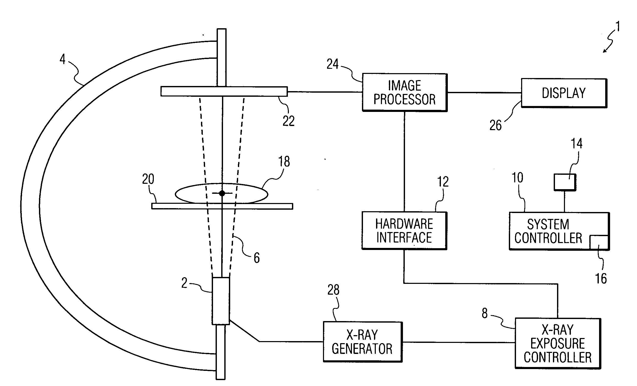
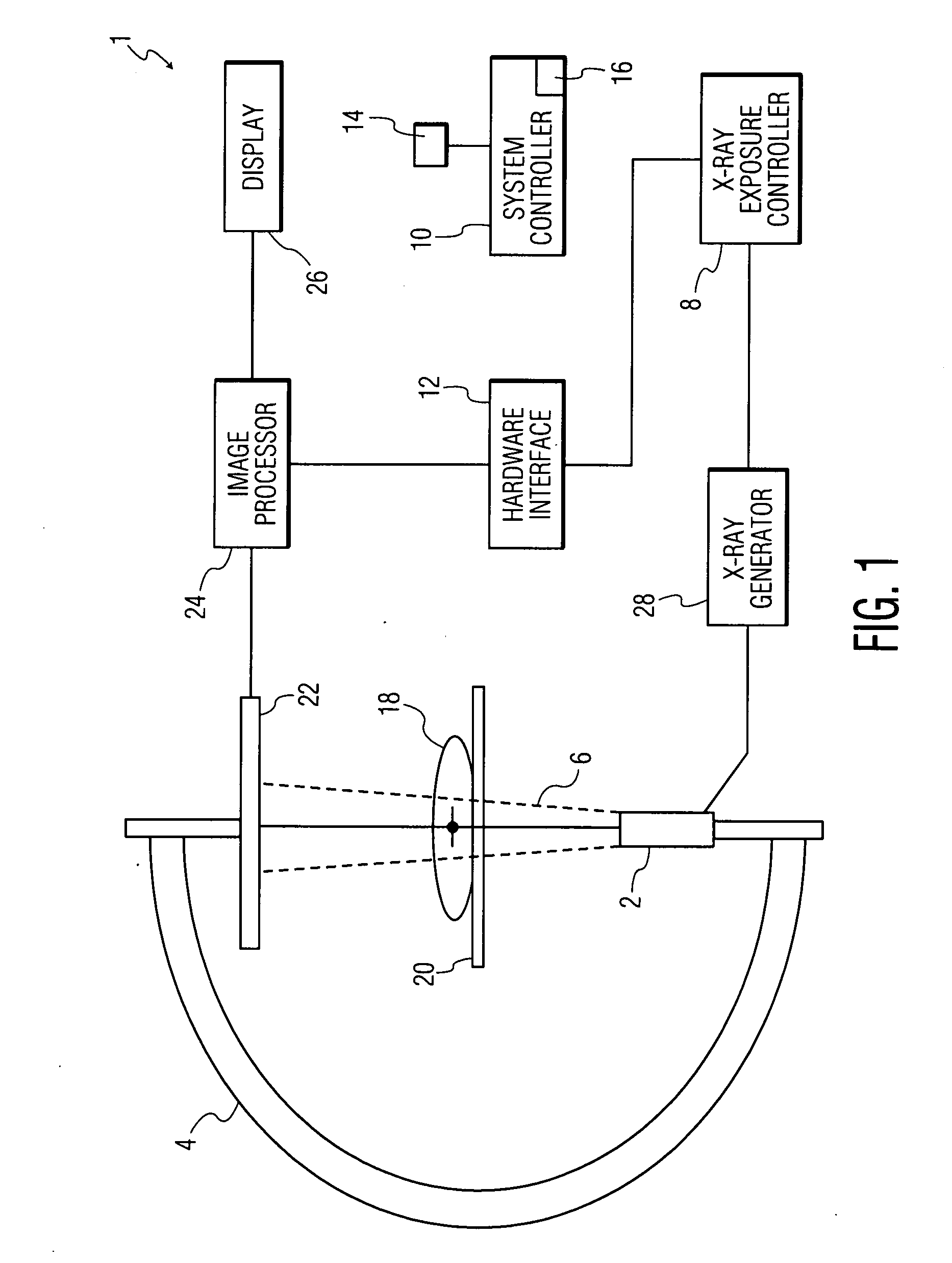
[0031]An “imaging system” is a system that includes at least a movable arm, an x-ray source, an x-ray detector, a display and a system controller. A “patient 3-dimensional image data set” is a three dimensional numerical array whose elements hold the values of specific physical properties at points in space inside the patient's body. A “multiplanar reformation image (MPR)” is a planar cross-section of the patient 3-dimensional image data set generated by cutting through the three-dimensional data set at some orientation (e.g., axial, coronal, sagittal, or oblique). A “fluoroscopic image” is a two-dimensional x-ray projection image showing internal tissues of a region of the body. A “live fluoroscopic image” is a sequence of x-ray images taken successively showing live movement of internal tissues of a region of the body. A “combined image” is an image in which an x-ray image is combined with an MPR or three-dimensional rendering of a three-dimensional data set. “Co-regist...


PUM

PropertyMeasurementUnit
angleaaaaaaaaaa
sizeaaaaaaaaaa
imagingaaaaaaaaaa

Abstract

A system and method are disclosed for planning a percutaneous procedure and for guiding an instrument to engage a target within a patient's body. A patient 3-dimensional image data set is provided, within which a user selects a skin entry point and a target point. A line, or “planned path,” is generated between the points which is used to align a movable arm to achieve a “Bull's Eye View,” in which the two points are superimposed. The instrument is placed at the skin entry point and aligned using the Bull's Eye View along a desired trajectory that intersects the target. Initial alignment is verified using fluoroscopy. Progression fluoroscopic views are used during the insertion procedure to ensure the instrument remains on the planned path. When the instrument reaches the target, a procedure may be performed, such as a biopsy, a drainage procedure, a radiofrequency ablation, or other medical interventional procedure.

Description

CROSS-REFERENCE TO RELATED APPLICATIONS[0001]This is a non-provisional application of pending U.S. provisional patent application Ser. No. 60 / 992,830, filed Dec. 6, 2007 by Strobel et al., the entirety of which application is incorporated by reference herein.FIELD OF THE DISCLOSURE[0002]The disclosure is related to methods for performing percutaneous procedures, and more particularly to improved guidance methods for percutaneous procedures utilizing movable arm fluoroscopic devices.BACKGROUND[0003]Percutaneous procedures, such as needle biopsies, drainages, radiofrequency ablations, and other medical interventional procedures, are often performed using X-ray fluoroscopy devices. In an attempt to reduce procedure times as well as radiation exposure to both the user and the patient, while improving targeting accuracy, the use of laser pointer devices has been proposed. The laser pointer may be mounted on the C-arm and aligned with a pair of points, one on the skin entry position and a...

Claims


Application Information

Patent Timeline
Patent Type & Authority Applications(United States)
IPC IPC(8): G06K9/00G01N23/04H05G1/60G06T15/00
CPCA61B6/12A61B6/4441A61B6/5217A61B6/5235G06T2219/028G06T19/00G06T2210/41A61B6/027A61B6/5247G16H50/30
Inventor STROBEL, NORBERTGALANT, ADAM K.YATZIV, LIRON
Owner SIEMENS CORP
Why Eureka
Try Eureka