Optical communication system

a communication system and optical communication technology, applied in the field of optical communication networks, can solve the problems of impairment, channel requires bidirectional or counter-propagation, and source is typically expensive, and achieve the effect of avoiding optical beat interference nois

Inactive Publication Date: 2010-05-06
UNIV COLLEGE CORK NAT UNIV OF IRELAND CORK
View PDF6 Cites 21 Cited by
  • Summary
  • Abstract
  • Description
  • Claims
  • Application Information

AI Technical Summary

Benefits of technology

[0011]According to the invention, there is provided an optical transmitter of the reflective modulation type, the transmitter having a means of generating reflection, a mixer for mixing a data stream and a sub-carrier, and an optical modulator for modulating an optical carrier with the output from the mixer in order to avoid optical beat-interference noise.
[0012]In one embodiment, the modulator is of the interferometric type, comprising means for suppressing the optical carrier at the transmitter output in order to reduce optical beat interference noise.
[0014]In one embodiment, the modulator comprises means for implementing CSS-AMPSK modulation, which suppresses optical beat noise and achieves strong dispersion tolerance.

Problems solved by technology

This can have major cost advantages as such sources are typically expensive.
However, a disadvantage of such networks is that the upstream channel requires bidirectional or counter-propagation of light with the same centre wavelength in the network (the carrier and the upstream signals).
Hence the systems are susceptible to interferometric beat noise generated by Rayleigh back-scattering (RB) and back-reflections from components in the fibre path, which can lead to impairments [2, 3] if suitable mitigation schemes are not employed.
This can lead to Rayleigh scattering-induced noise that may prevent operation of the network.
In bidirectional optical communication schemes Rayleigh backscattering can lead to dramatic signal impairments that, if not controlled, can render the system inoperable.
These fluctuations lead in turn to noise in the receiver photocurrent, and the portion of this noise that falls within the receiver bandwidth can generate errors in the signal transmission.
However, in schemes such as those shown in FIGS. 2 and 3 where there is bidirectional propagation in the fibre at the same wavelength then simple optical filtering is not possible and Rayleigh-induced impairments can occur.

Method used


Image

  • Optical communication system
  • Optical communication system
  • Optical communication system

Examples


Embodiment Construction

[0024]The invention will be more clearly understood from the following description of some embodiments thereof, given by way of example only with reference to the accompanying drawings in which:—

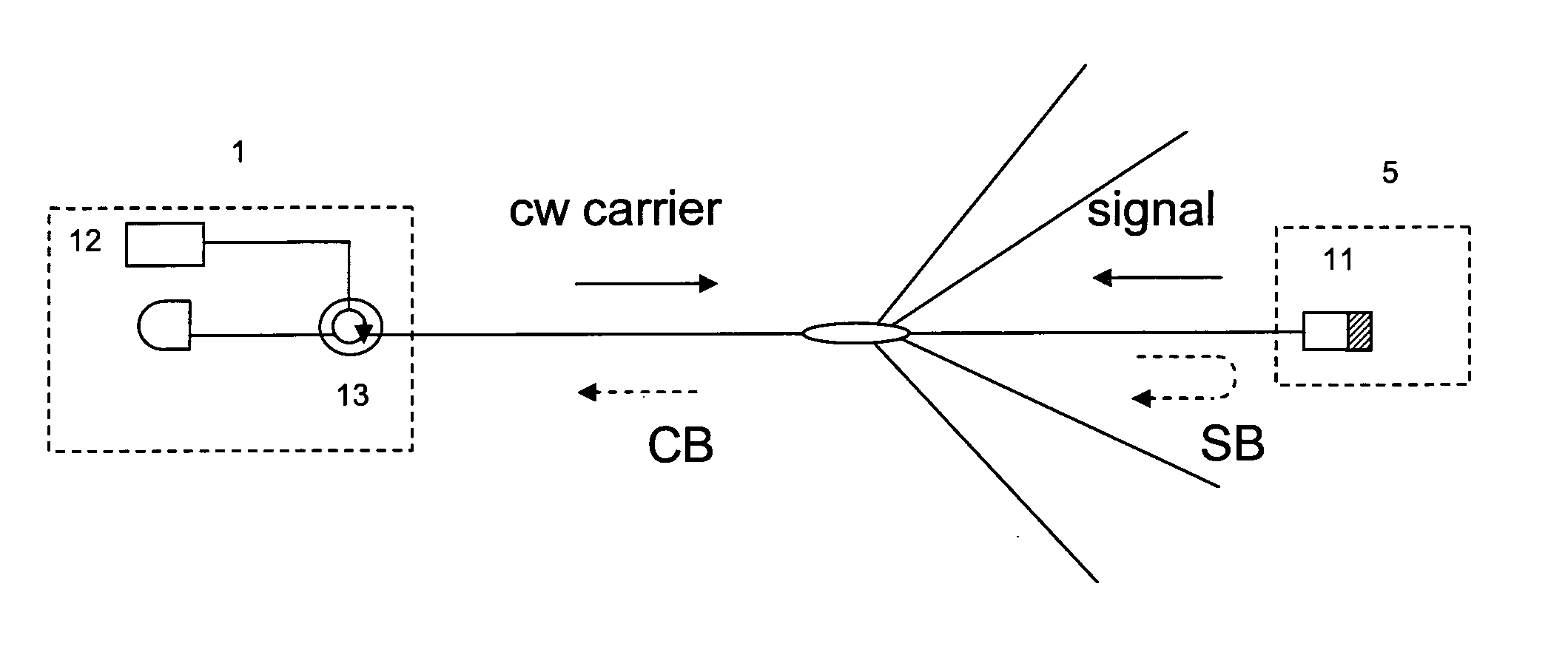
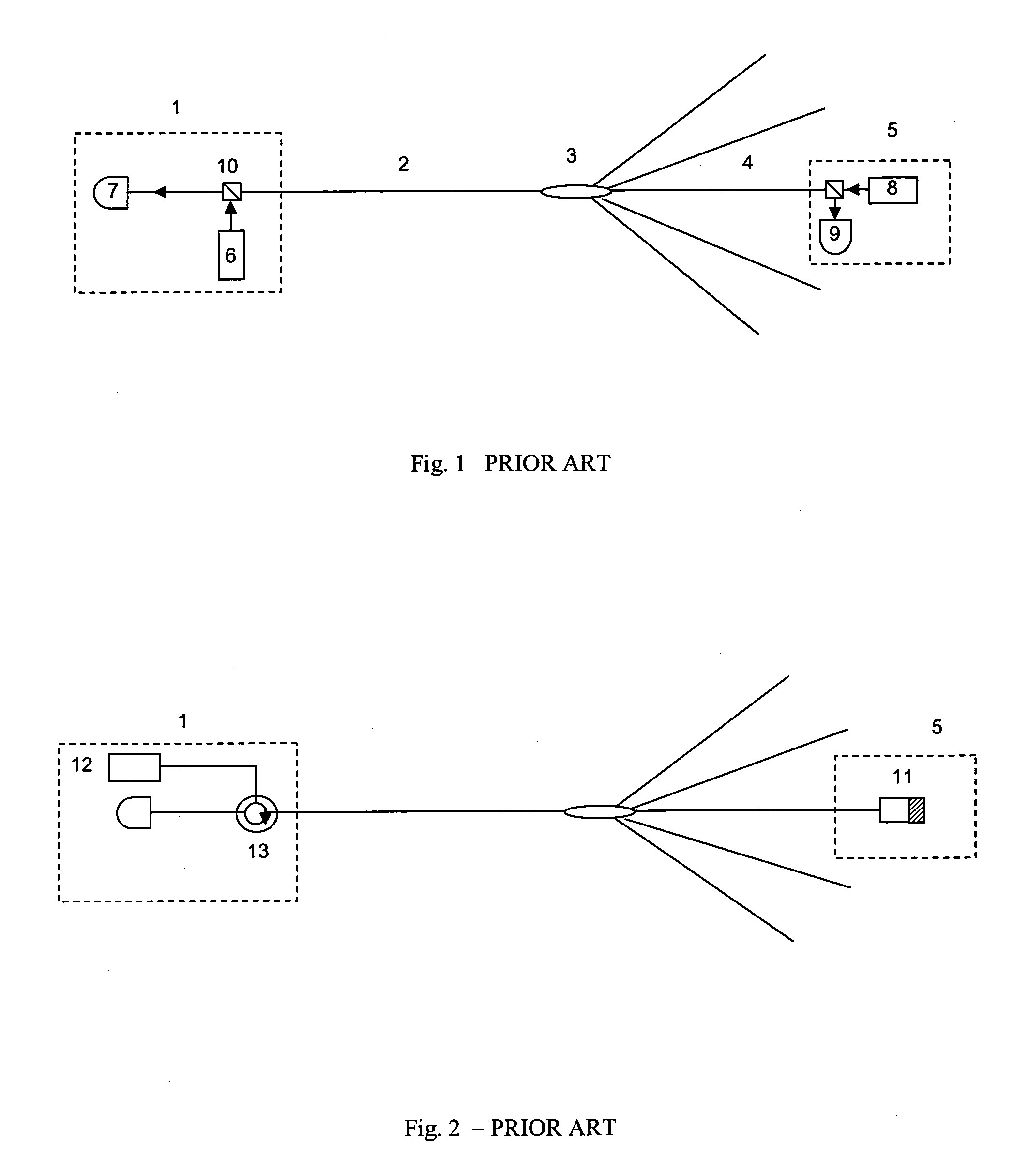
[0025]FIGS. 1 to 3 are diagrams concerning the prior art, as set out above;

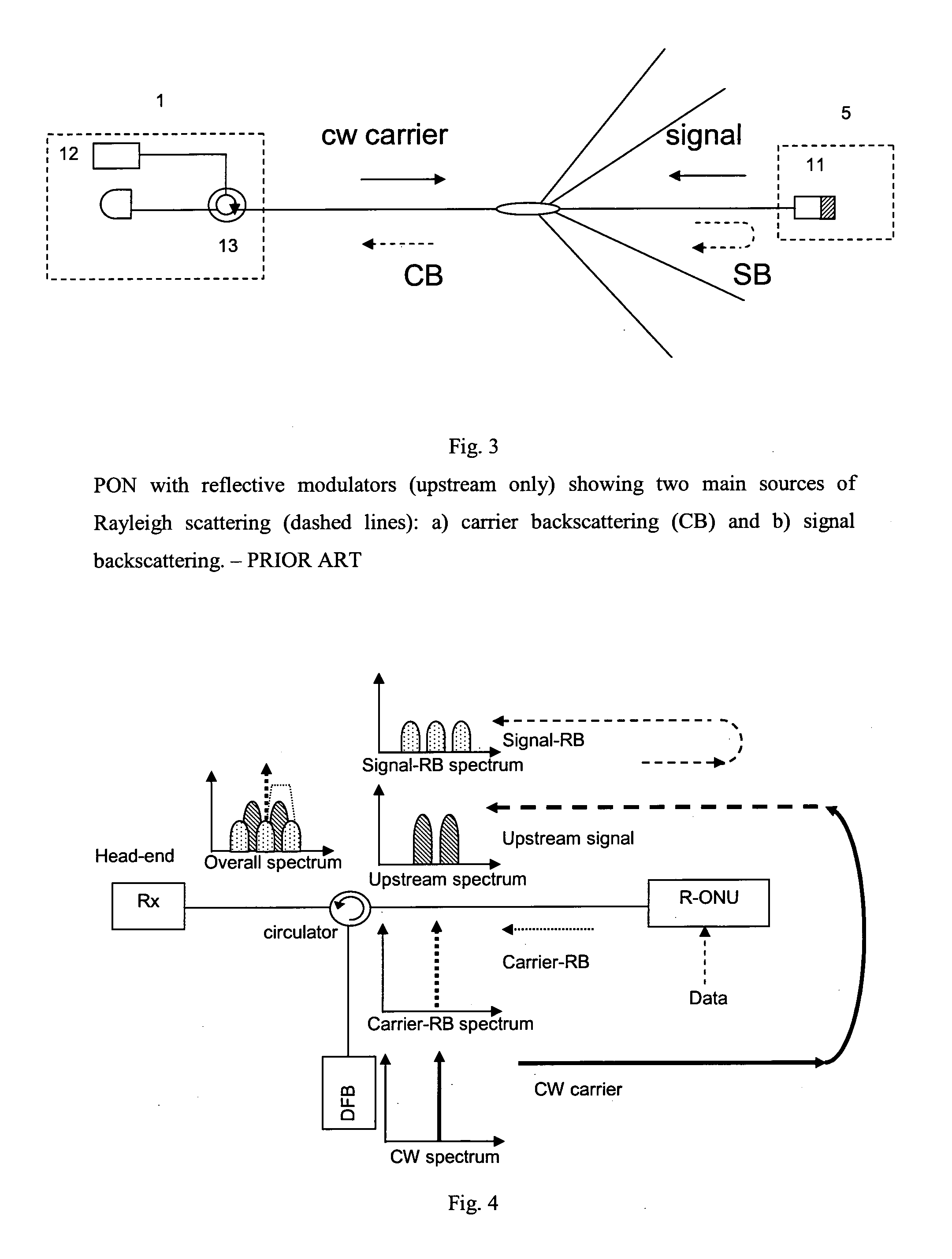
[0026]FIG. 4 is a diagram showing a modulation scheme of the invention in a PON;

[0027]FIGS. 5 to 7 are diagrams showing further embodiments; and

[0028]FIGS. 8 to 10 are plots showing experimental and simulation results demonstrating advantages of the invention.

[0029]An optical transmitter of the invention is of the reflective modulation type. The transmitter has a means of generating reflection, a mixer for mixing a data stream and a sub-carrier, and an optical modulator for modulating an optical carrier with the output from the mixer in order to avoid optical beat-interference noise arising from, for example, Rayleigh backscattering.

[0030]The modulator is in one embodiment of the interferometric type such as a Mach-Ze...


PUM


Abstract

An optical transmitter is of the reflective modulation type and has a means of generating reflection, a mixer for mixing a data stream and a sub-carrier, and an optical modulator for modulating an optical carrier with the output from the mixer in order to avoid optical beat-interference noise arising from, for example, Rayleigh backscattering. The modulator is in one embodiment of the interferometric type such as a Mach-Zehnder Modulator (MZM) operated to suppress the optical carrier at the transmitter output in order to reduce optical beat interference noise. The modulator preferably implements CSS-AMPSK modulation, which suppresses optical beat noise and achieves strong dispersion tolerance, enabling, for example, 10 Gb / s data transmission over 100 km distance without dispersion compensation. The transmitter may have a duobinary encoder, which encodes the data prior to mixing with the sub-carrier.

Description

[0001]The invention relates to optical communication networks such as passive optical networks (PONs).[0002]FIG. 1 shows a conventional PON which consists of a network head end station (1), which is linked by means of a feeder fibre (2) to a passive optical splitter (3), the outputs of which are connected by means of drop fibres (4) to a plurality of end user stations (5). The head end station contains a laser source (6) for generating downstream signals and an optical receiver (7) for detecting upstream signals. Similarly the end user stations contain a laser (8) for generating upstream signals and an optical receiver (9) for detecting downstream signals. Typically the upstream and downstream communication channels operate at different wavelengths, λup, and λdown, so that they can be combined and separated using optical filters (10) known as wavelength division multiplexers (WDMs). To avoid contention and cross talk a time-division-multiple-access protocol is employed on the networ...

Claims


Application Information

Patent Timeline
Patent Type & Authority Applications(United States)
IPC IPC(8): H04B10/04H04B10/2587
CPCH04B10/2587
Inventor CHOW, CHI WAITALLI, GIUSEPPEELLIS, ANDREWTOWNSEND, PAUL
Owner UNIV COLLEGE CORK NAT UNIV OF IRELAND CORK
Why Eureka
Try Eureka