

Bearing device of gas turbine power generation equipment and gas turbine power generation equipment
a technology of power generation equipment and bearings, which is applied in the direction of bearing cooling, machines/engines, liquid fuel engines, etc., can solve the problems of increasing the power of the pump, increasing the power consumption of auxiliaries, and increasing the power loss of the bearing
- Summary
- Abstract
- Description
- Claims
- Application Information
AI Technical Summary
Benefits of technology
Problems solved by technology
Method used
Image

Examples
Embodiment Construction
[0039]One embodiment of the present invention will hereinafter be described with reference to the drawings.
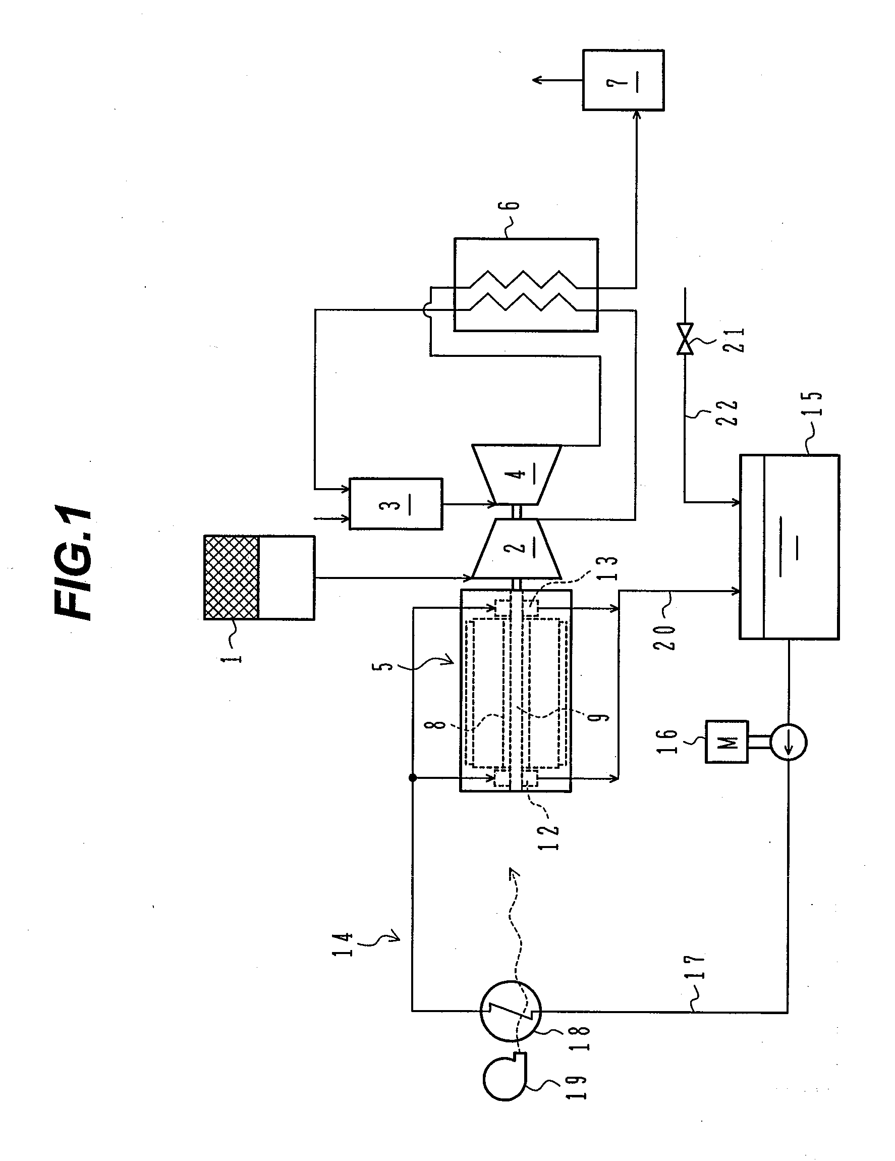
[0040]FIG. 1 is a schematic diagram illustrating the entire configuration of an embodiment of gas turbine power generation equipment according to the present invention along with a water circulation system.
[0041]Referring to FIG. 1, gas turbine power generation equipment is used as e.g. privately-owned power generation equipment with a capacity of about 100 to 250 kW. This gas turbine power generation equipment includes a compressor 2 which compresses air (the atmosphere) sucked through an air intake filter 1; a combustor 3 which mixes the compressed air created by the compressor 2 with fuel for combustion; a turbine 4 which is rotationally driven by combustion gas from the combustor 3; a generator 5 which converts part of the rotational power of the turbine 4 into electric energy; a regenerating heat exchanger 6 which heats the compressed air fed from the compressor 2 to the c...
PUM
 Abstract
Description
Claims
Application Information