Refrigerant compressor

a compressor and refrigerant technology, applied in the direction of positive displacement liquid engines, pumping, lighting and heating apparatus, etc., can solve the problems of insufficient effect, difficult processing, and difficult assembly process, so as to reduce the amount of heat generated, simplify the assembly process, and suppress the temperature increase in the vicinity of the stationary ring

Active Publication Date: 2010-05-06
MITSUBISHI HEAVY IND LTD
View PDF4 Cites 34 Cited by
  • Summary
  • Abstract
  • Description
  • Claims
  • Application Information

AI Technical Summary

Benefits of technology

[0007]Moreover, it is necessary to form an oil circulation passage that passes through the oil accommodating space. This becomes a design constraint. In addition, since the oil supply direction of the oil to the contact sliding parts is from the center of the mechanical seal toward the outer circumference of the mechanical seal, it is necessary to process the discharge surface so that it allows the leaked oil to easily move away from the vicinity of the contact sliding parts, which requires the same processing accuracy as for a surface facing the sliding surface of the stationary ring side face, so the problem arises that the processing is difficult. Another problem is that although the above-described effect may be expected in the case of the configuration in which the oil supply direction to the contact sliding parts is from the center toward the outer circumference of the mechanical seal, a sufficient effect cannot be expected where the oil supply direction is from the outer circumference toward the center.
[0036]Assembling of the compressor according to the invention can be done easily. Moreover, the lubricating oil leaking from the mechanical seal can be quickly guided to the oil discharge hole and discharged therefrom, or the temperature increase due to the heat generation in the vicinity of the stationary ring from which the lubricating oil leaks out can be suppressed. Therefore, the leaked oil does not stay around the stationary ring of the mechanical seal, and it is not exposed to a high temperature. Thus, it is possible to resolve the problems of the prior art such as degradation in the shaft sealing capability and acceleration of the lubricating oil leakage caused by the leaked oil turning into sludge, building up, and being caught between the contact sliding parts. The invention prevents leaked oil from turning into sludge, which is an advantageous effect especially since the current trend is toward increased use of a high pressure refrigerant, which increases the amount of heat generated at the contact sliding portions.

Problems solved by technology

Therefore, the problem arises that the assembling process is difficult.
In addition, since the oil supply direction of the oil to the contact sliding parts is from the center of the mechanical seal toward the outer circumference of the mechanical seal, it is necessary to process the discharge surface so that it allows the leaked oil to easily move away from the vicinity of the contact sliding parts, which requires the same processing accuracy as for a surface facing the sliding surface of the stationary ring side face, so the problem arises that the processing is difficult.
Another problem is that although the above-described effect may be expected in the case of the configuration in which the oil supply direction to the contact sliding parts is from the center toward the outer circumference of the mechanical seal, a sufficient effect cannot be expected where the oil supply direction is from the outer circumference toward the center.

Method used


Image

  • Refrigerant compressor
  • Refrigerant compressor
  • Refrigerant compressor

Examples


first embodiment

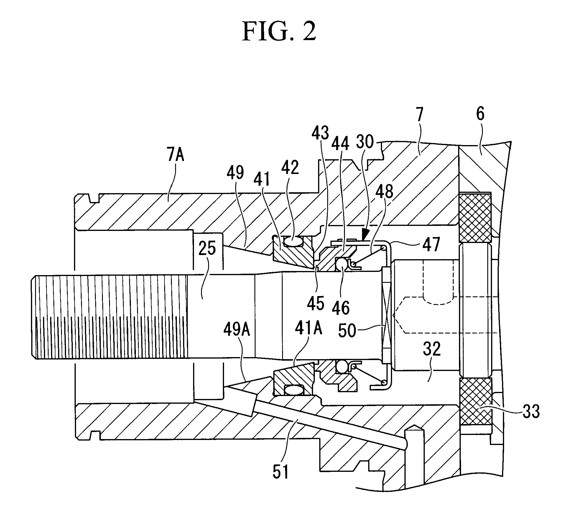
[0065]Hereinbelow, a first embodiment of the invention will be described with reference to FIGS. 1 and 2.

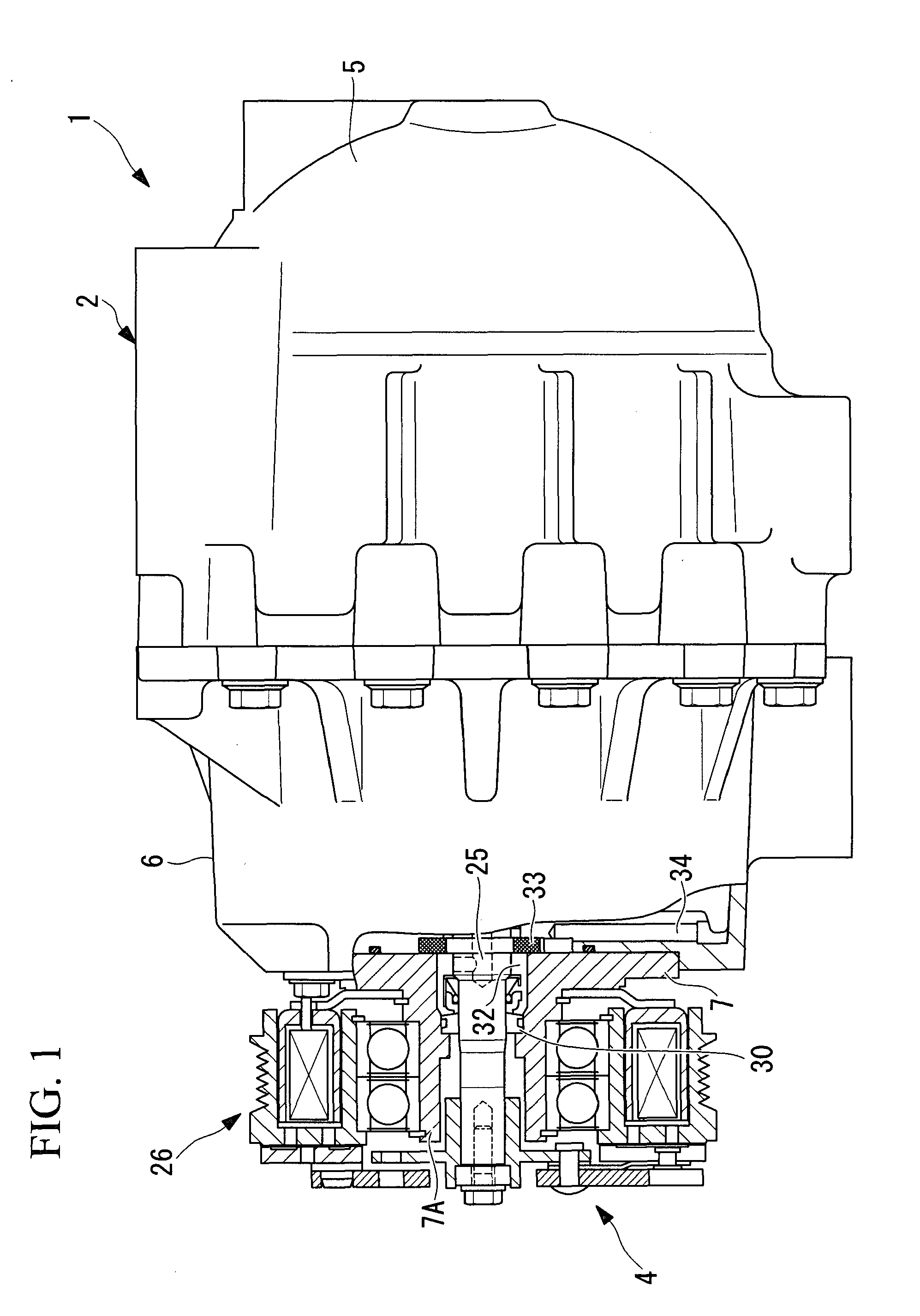
[0066]FIG. 1 shows the outer appearance, partly in section, of a refrigerant compressor according to the first embodiment of the invention. A refrigerant compressor 1 has a cylindrical housing 2 extending horizontally. The housing 2 is constructed by integrally coupling a rear housing 5, a front housing 6, and a drive unit housing 7.

[0067]A compression mechanism, not shown, for compressing refrigerant gas is incorporated in the internal space of the housing 2. This compression mechanism may be any type of compression mechanism, such as a publicly-known swash plate type, a rotary type, or a scroll type compression mechanism. The housing 2 is provided with a suction port, not shown, for sucking a low-pressure refrigerant gas, and a discharge port, not shown, for discharging the high-temperature and high-pressure refrigerant gas that has been compressed. In the interior of the housi...

second embodiment

[0083]Next, a second embodiment of the invention will be described with reference to FIG. 3.

[0084]The present embodiment differs from the foregoing first embodiment in that the structure of the stationary ring 41 of the mechanical seal 30 is partially changed. In other respects, this embodiment is the same as the first embodiment, so the description thereof will be omitted.

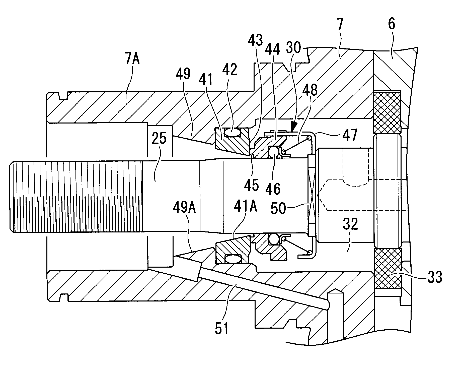
[0085]FIG. 3 shows a vertical cross-sectional view of the inner structure of the drive unit housing 7 portion. In the present embodiment, the inner diameter D1 of the sliding protuberance 45 provided for the rotary ring 44 and the inner diameter D2 of the inner circumferential surface of the stationary ring 41 are made approximately equal to each other. The inner diameter D1 of the sliding protuberance 45 and the inner diameter D2 of the inner circumferential surface of the stationary ring 41 are preferably set so as to satisfy the expression (D1−D2) / D1≦0.07.

[0086]In the above-described embodiment, the inner diame...

third embodiment

[0089]Next, a third embodiment of the invention will be described with reference to FIG. 4.

[0090]The present embodiment has a different structure for transferring leaked oil from the mechanical seal 30 to the oil discharge hole 51 from that of the foregoing first embodiment. In other respects, this embodiment is the same as the first embodiment, so the description thereof will be omitted.

[0091]As shown in FIG. 4, the present embodiment has a configuration in which leaked oil is transported in a helical groove 52 on the outer circumferential surface of the rotating shaft 25 extending the entire way from the portion outward from where of the mechanical seal 30 is set to a position corresponding to the oil discharge hole 51 or a part thereof, by rotation of the rotating shaft 25.

[0092]With the above-described configuration, even if lubricating oil leaks out from between the contact sliding portions of the mechanical seal 30 to the inner circumferential side of the stationary ring 41, t...


PUM


Abstract

A refrigerant compressor is provided that can be assembled easily and can quickly discharge lubricating oil that leaks from contact sliding parts of its mechanical seal so as to prevent the oil from turning into sludge around the stationary ring. In a refrigerant compressor in which a mechanical seal which shaft seals the inner side and the outer side of a housing is installed at a portion of the housing through which a rotating shaft penetrates, a mechanical seal comprises a stationary ring securely fastened to the inner circumferential surface of a boss portion, a rotary ring securely fastened to the outer circumferential surface of the rotating shaft to the inside of the stationary ring so as to face the stationary ring, whereby sliding contact is formed between sides of the stationary ring and the rotary ring. The inner circumferential surface of the boss portion to the outside of the stationary ring is provided with an inclined portion over the entire circumference or at least the gravitationally lower portion of the inner circumferential surface, which enlarges from the stationary ring side toward an oil discharge hole to the outside of the stationary ring.

Description

TECHNICAL FIELD[0001]The present invention relates to a refrigerant compressor in which a mechanical seal is installed between the inner circumferential surface of a boss portion and the outer circumferential surface of a rotating shaft in a housing through which a rotating shaft penetrates, and shaft seals the inner side and the outer side (atmosphere side) of the housing.BACKGROUND ART[0002]Among refrigerant compressors, what is called an open-type refrigerant compressor has a housing in which a compression mechanism is accommodated and a rotating shaft one end of which protrudes from the housing toward the outside so that it is driven by an external drive source. In such an open-type refrigerant compressor, the portion of the housing through which the rotating shaft penetrates needs to be sealed so that the interior of the housing is hermetically sealed from the atmosphere. A mechanical seal has come to be used for the sealing, as high pressure refrigerants such as R410A and CO2 ...

Claims


Application Information

Patent Timeline
Patent Type & Authority Applications(United States)
IPC IPC(8): F04C28/00F04C27/00F04C29/04
CPCF04C27/009F25B31/002F16J15/3404
Inventor SATO, HAJIMEMARUIWA, YASUHARUKIMATA, YOSHIYUKIMIYAMOTO, YOSHIAKI
Owner MITSUBISHI HEAVY IND LTD
Why Eureka
Try Eureka