Mask fixing device in vacuum processing apparatus

a technology of mask fixing and vacuum processing, which is applied in the direction of vacuum evaporation coating, electrolysis components, coatings, etc., can solve the problems of increasing product cost, increasing tact time, and inability to cope with large-sized substrates, and achieves low cost, high accuracy, and aggravated accuracy

a technology of mask fixing and vacuum processing, which is applied in the direction of vacuum evaporation coating, electrolysis components, coatings, etc., can solve the problems of increasing product cost, increasing tact time, and inability to cope with large-sized substrates, and achieves low cost, high accuracy, and aggravated accuracy

US20100112194A1Inactive Publication Date: 2010-05-06CANON ANELVA CORP

Image

  • Mask fixing device in vacuum processing apparatus
  • Mask fixing device in vacuum processing apparatus
  • Mask fixing device in vacuum processing apparatus

Examples


Embodiment Construction

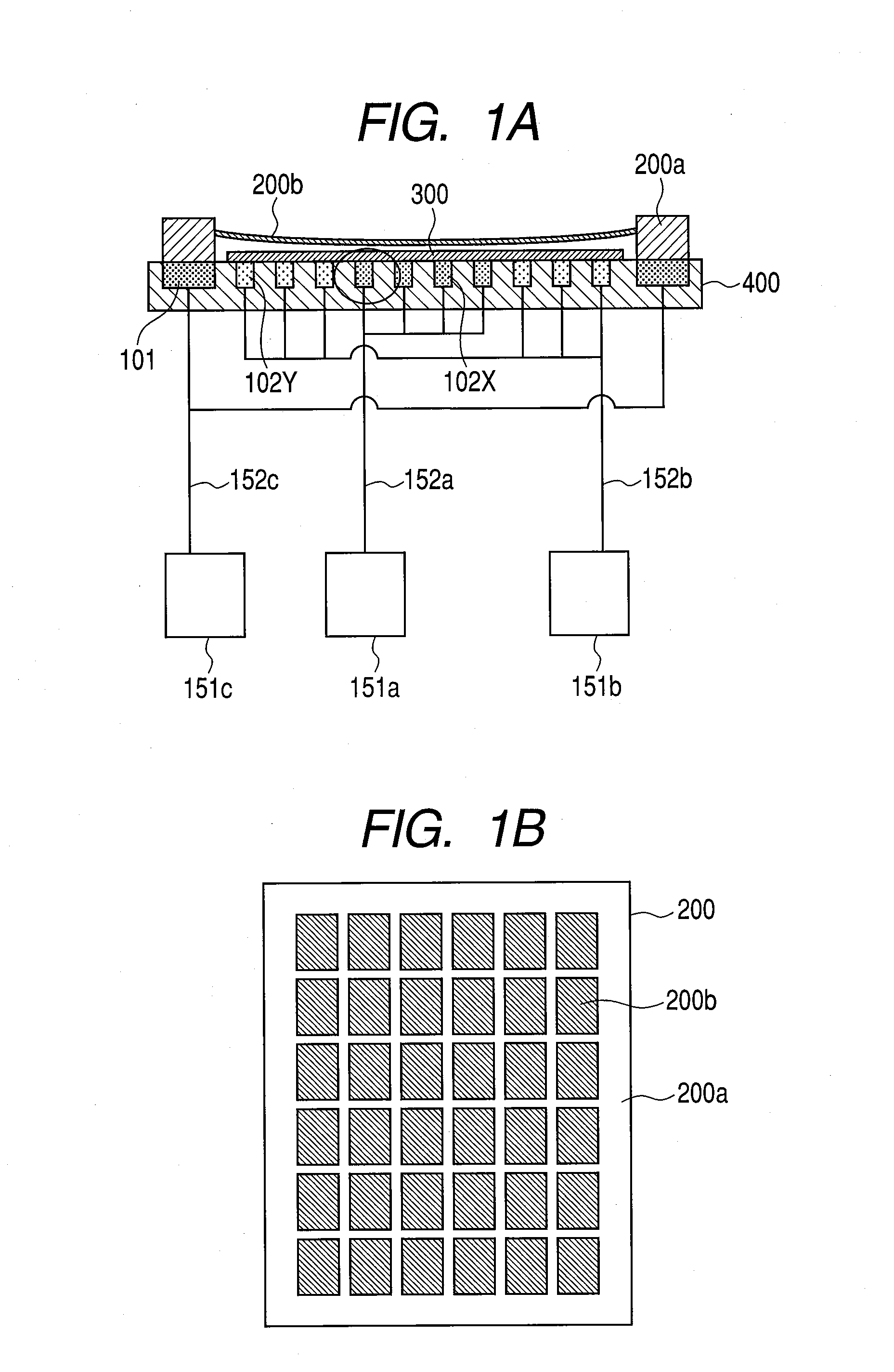
[0096]Exemplary embodiments according to the present invention will now be described below. FIG. 1A is a sectional (elevational) view illustrating a schematic structure of a base part of a vacuum processing apparatus according to a principle of the present invention. FIG. 1A illustrates a state of the vacuum processing apparatus at the time when the alignment of a mask 200 (including 200a and 200b) which will be described later with an object to be processed 300 has been finished, and the vapor-deposition is conducted in an upside-down state. The object to be processed 300 is arranged on an electro-permanent magnet 102 (including 102X and 102Y) which is arranged on a base 400, and the mask 200 is arranged thereon. The mask membrane plane 200b of the mask 200 is arranged in the upper part of the object to be processed 300 which is arranged on the electro-permanent magnet 102, and its periphery is surrounded by the mask frame 200a.

[0097]The mask 200 is structured by the mask frame 20...


PUM

PropertyMeasurementUnit
thicknessaaaaaaaaaa
weightaaaaaaaaaa
sizeaaaaaaaaaa

Abstract

A vacuum processing apparatus which processes an object to be processed with the use of a mask membrane plane of magnetic material and a mask frame of the magnetic material is characterized in that the mask of the magnetic material is attracted by an electro-permanent magnet that is disposed in an opposite side of the mask with respect to the surface having the object to be processed mounted thereon.

Description

CROSS-REFERENCES TO RELATED APPLICATIONS[0001]This application is a continuation application of International Application No. PCT / JP2008 / 056061, filed on Mar. 28, 2008, the entire contents of which are incorporated by reference herein.TECHNICAL FIELD[0002]The present invention relates to a vacuum processing apparatus, a method for manufacturing an image display apparatus using the vacuum processing apparatus, and an electronic device manufactured by the vacuum processing apparatus.BACKGROUND ART[0003]In a glass-substrate processing apparatus for a flat panel display represented by an organic electroluminescence device, a desired function is generally given to a substrate by forming a desired pattern of desired accuracy on the substrate. As a pattern-forming method, there are a vacuum vapor-deposition method, a sputtering method, a photolithographic method, a screen printing method and the like. However, an accuracy of higher definition in pattern-forming is required to a pattern for...

Claims


Application Information

Patent Timeline
06 May 2010
Publication
US20100112194A1
IPC
B05D5/06; C23C14/24; C23C14/34
CPC
C23C14/042; C23C16/042; C23C14/048
Inventors
INOUE, MASATO; MATSUI, SHIN