Systems and methods for reactive distillation with recirculation of light components

a technology of reactive distillation and light components, which is applied in the direction of energy input, sustainable manufacturing/processing, and separation processes, etc., can solve the problems of undesirable high molecular weight products, low efficiency, and wide variety of molecular weight compounds within the reactor

Inactive Publication Date: 2010-05-06
STICKNEY MICHAEL J +1
View PDF1 Cites 22 Cited by
  • Summary
  • Abstract
  • Description
  • Claims
  • Application Information

AI Technical Summary

Benefits of technology

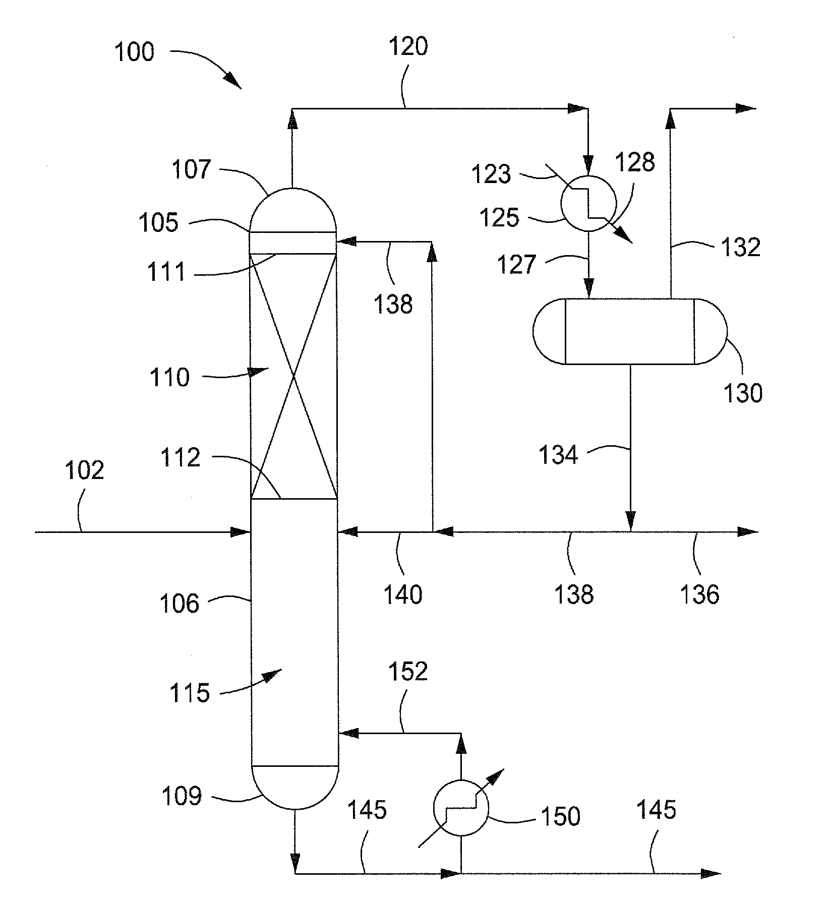
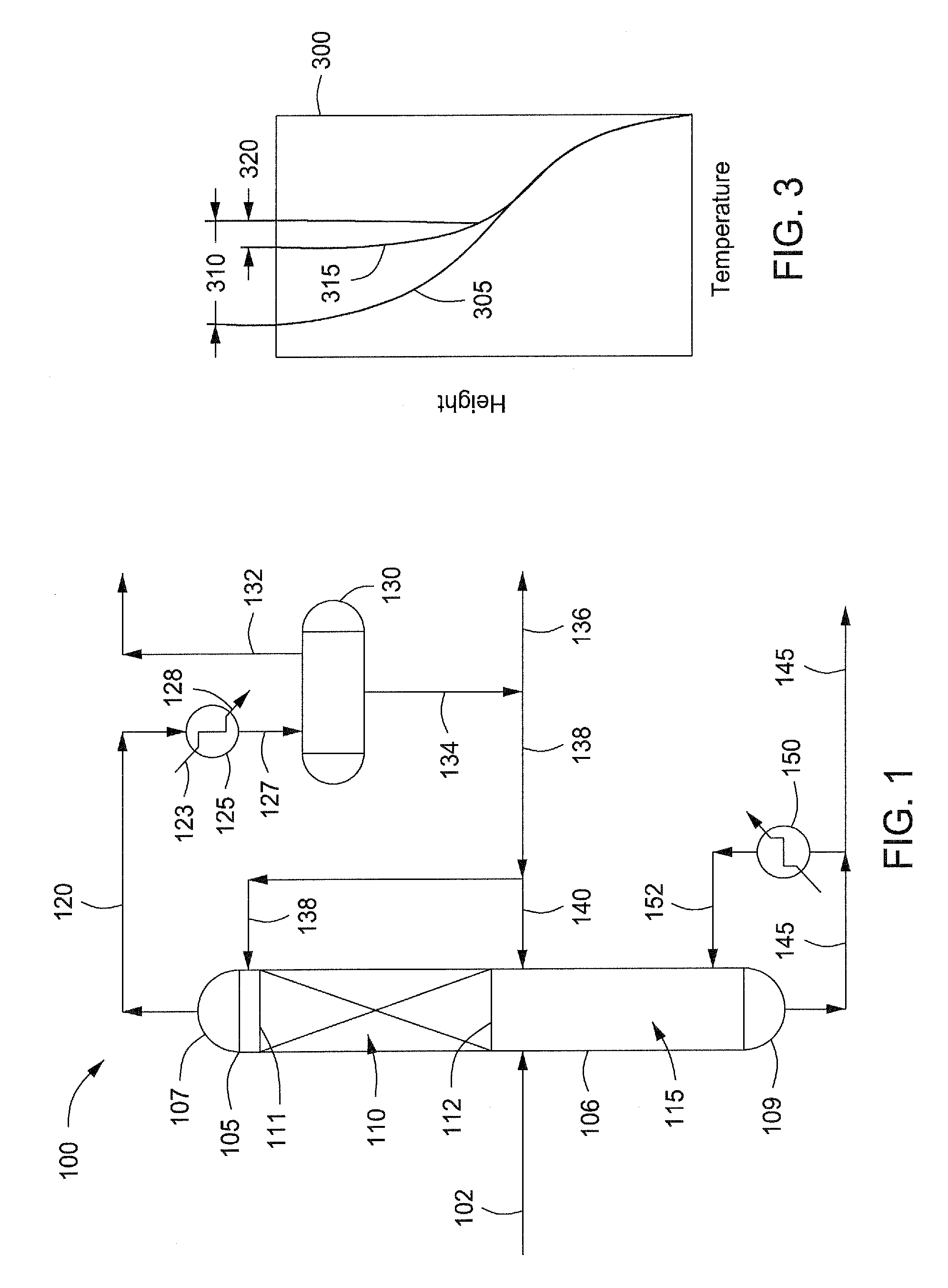
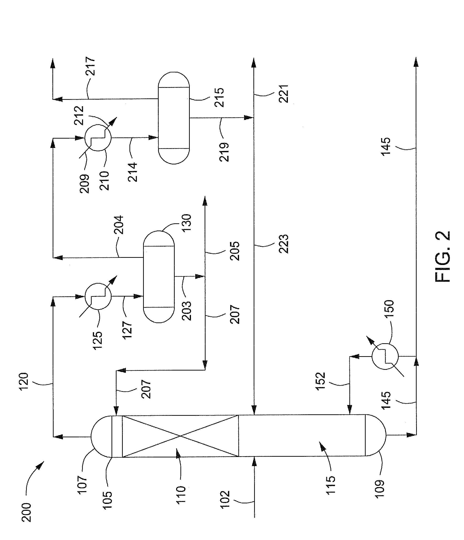
[0009]Systems and methods for producing gas-to-liquids products using reactive distillation are provided. In at least one specific embodiment, the method for producing gas-to-liquids products can include reacting a feedstock in a column having a distillation zone and a reaction zone to provide a bottoms stream and an overhead stream. In one or more embodiments, a first portion of the overhead stream can be recycled to the column at the top of the reaction zone. In one or mole embodiments, a second portion of the overhead stream can be recycled to the column at the bottom of the reaction zone.
[0010]In at least one other specific embodiment, the method for producing gas-to-liquids products can include introducing one or more reactants to a reactive distillation column containing a reaction zone and a distillation zone therein. In one or more embodiments, the one or more reactants can be reacted in the presence of a catalyst in the reaction zone to provide an overhead and an intermediate product. In one or more embodiments, the intermediate product can be selectively separated into two or more distillate fractions. In one or more embodiments, the overhead can be separated into a

Problems solved by technology

A disadvantage, however, of using a fixed bed or slurry reactor configuration is that a wide variety of molecular-weight compounds are present within the reactor at one time.
There is little control over chain growth in a fixed bed or slurry reactor, which causes undesirable high molecular-weight products, such as heavy hydrocarbon waxes to be produced.
These waxy products are prone to poisoning and/or fo

Method used


Image

  • Systems and methods for reactive distillation with recirculation of light components
  • Systems and methods for reactive distillation with recirculation of light components
  • Systems and methods for reactive distillation with recirculation of light components

Examples


example 1

[0077]The same reactor configuration and catalyst were used as described above in the previous comparative example. This time a secondary recycle was fed to the column.

[0078]After a stable temperature profile within the reaction bed was achieved, i.e. the temperature difference from a first end of the reaction bed (curve 610) to a second end of the reaction bed (curve 605), was about 110° F. or less, the reactants were introduced to the reaction bed, which occurred at about 4 hours. The reactants were a 2:1 mixture of H2 and CO.

[0079]FIG. 6 is a graphical representation of the reaction bed temperature versus time for the reaction bed with the secondary recycle. FIG. 7 is a graphical representation of column pressure versus time for an illustrative reaction bed with the secondary recycle. As the ethylene and propylene levels in the overhead increased, the temperature at the bottom of the reaction bed remained at 400° F. (curve 605), the temperature at the top of the reaction bed bega...


PUM

PropertyMeasurementUnit
Temperatureaaaaaaaaaa
Fractionaaaaaaaaaa
Temperatureaaaaaaaaaa

Abstract

Systems and methods for producing gas-to-liquids products using reactive distillation are provided. The method for producing gas-to-liquids products can include reacting a feedstock in a column having a distillation zone and a reaction zone to provide a bottoms stream and an overhead stream. A first portion of the overhead stream can be recycled to the column at the top of the reaction zone and second portion of the overhead stream can be recycled to the column at the bottom of the reaction zone.

Description

FEDERALLY SPONSORED RESEARCH OR DEVELOPMENT[0001]This invention was made, in part, with support awarded by the United States Department of Energy under Grant No.: DE-FG02-0404ER83999. The United States government may have certain rights in this invention.BACKGROUND OF THE INVENTION[0002]1. Field of the Invention[0003]Embodiments of the present invention generally relate to systems and methods for producing gas-to-liquids products. More particularly, embodiments relate to systems and methods for producing gas-to-liquids products using reactive distillation.[0004]2. Description of the Related Art[0005]Hydrocarbon gases can be reacted to provide liquid hydrocarbon materials, such as diesel and / or gasoline components, and other useful products. Such reactions are typically catalyzed using Fixed bed or slurry reactors. A disadvantage, however, of using a fixed bed or slurry reactor configuration is that a wide variety of molecular-weight compounds are present within the reactor at one ti...

Claims


Application Information

Patent Timeline
IPC IPC(8): C07C1/00B01D3/00B01D3/34
CPCB01D3/14B01D3/4205C07C1/048C07C11/04C07C11/06Y02P20/127Y02P20/10
Inventor STICKNEY, MICHAEL J.JONES, JR., EDWARD M.
Owner STICKNEY MICHAEL J
Why Eureka
Try Eureka