Phase change cooler and electronic equipment provided with same

a technology of electronic equipment and cooler, which is applied in the direction of lighting and heating apparatus, semiconductor devices, basic electric elements, etc., can solve the problems of inability to extend the pipe upward and install the condenser, unavoidable condensation in the pipe, and difficulty in using it for various purposes, etc., to achieve the effect of reducing size, high working ratio and reliable cooling of parts

Active Publication Date: 2013-01-31
NEC CORP
View PDF25 Cites 24 Cited by
  • Summary
  • Abstract
  • Description
  • Claims
  • Application Information

AI Technical Summary

Benefits of technology

[0023]According to the phase change cooler of the present invention, in the case of the working ratio of a certain one part being in a high state, not only is the refrigerant supplied from the liquid tube to the heat receiving unit at which more refrigerant, upon receiving the heat from that part, evaporates, but the refrigerant is also supplied from the adjacent heat receiving unit via the bypass tube. Accordingly, it is possible to more reliably cool a part with a high working ratio.
[0024]Also, according to the phase change cooler of the present invention, it is possible to make the number of heat radiating units fewer than the number of heat receiving units, and reduction in size and simplification of the cooling structure is achieved from the standpoint of the entire device. For example, by collecting the vapor from a plurality of heat receiving units into one heat radiating unit, not only is a reduction in cost achieved due to the fewer number of parts, but it is also possible to achieve a power saving due to the fewer number of fans that constitute the heat radiating unit.

Problems solved by technology

For that reason, this ebullient cooler is expensive when miniaturizing it for electronic components, and so using it for various purposes is difficult.
However, in an electronic apparatus, it is not always possible to extend a pipe upward and install the condenser due to the internal layout.
Also, in the case of installing the pipe that is to be connected to the condenser vertically upward from an evaporator, it is unavoidable for condensation to occur in the pipe.
This not only becomes resistance to the vapor that is heading toward the condenser, but also reduces the cross-sectional area of the evaporation path, thus producing pressure loss.
As a result, not only is the performance of the condenser not exploited, but its operation as a cooler becomes unstable.
Moreover, in the worst case, there is the risk of drying out of the evaporator being induced.
However, this kind of structure is not suitable for the flow of refrigerant of both the liquid phase and the gaseous phase.
Also, in the evaporator, heat reception is not performed over the entire heat generation surface.
However, as a cooling structure, it becomes complicated and expensive.
The structure for heating makes the structure of the cooler more complicated and expensive.
Moreover, there is the problem of the load on the heat radiating unit becoming unnecessarily large.
The heat radiating unit is designed so as to dissipate the entire quantity of heat that is collected, but the heat dissipation efficiency is worse compared to the case of dissipating heat without the heat radiating units being aggregated.

Method used


Image

  • Phase change cooler and electronic equipment provided with same
  • Phase change cooler and electronic equipment provided with same
  • Phase change cooler and electronic equipment provided with same

Examples


first exemplary embodiment

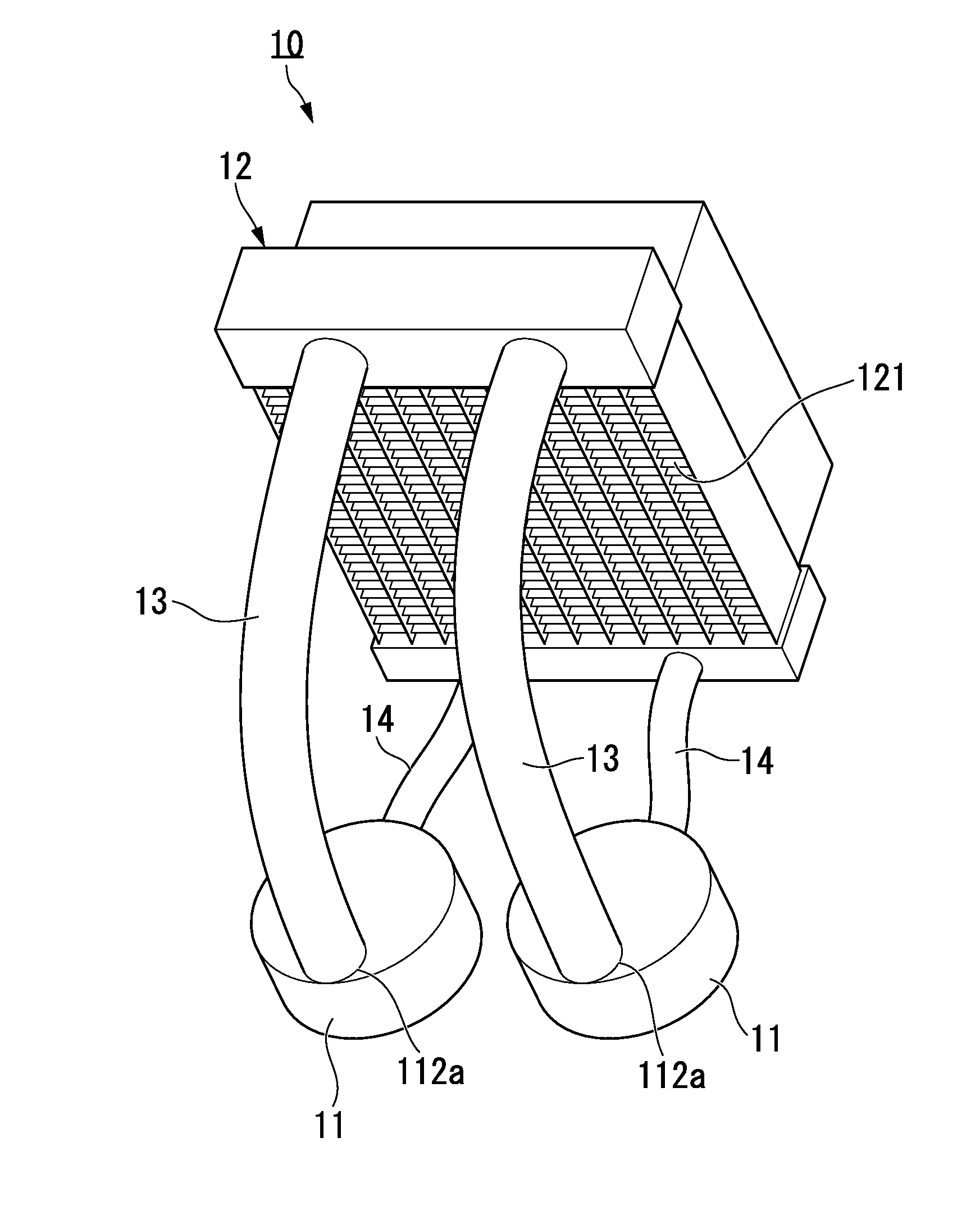
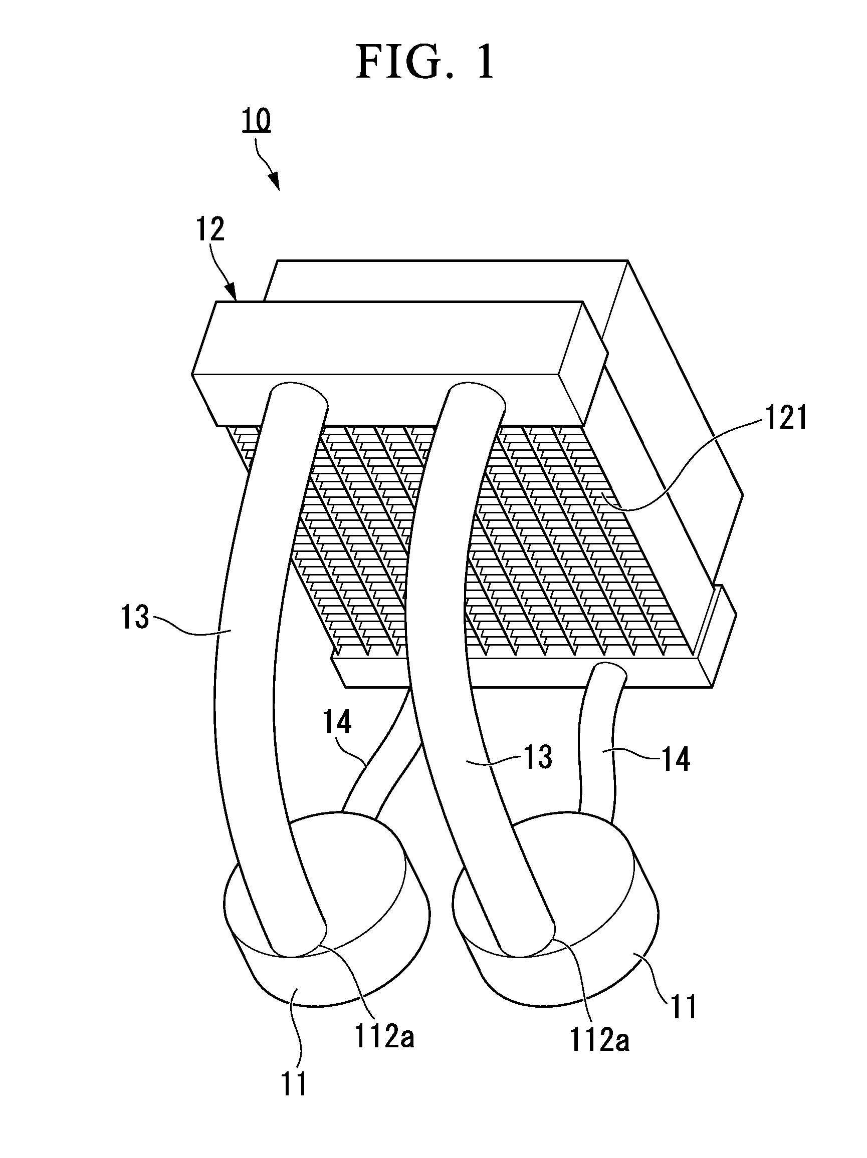
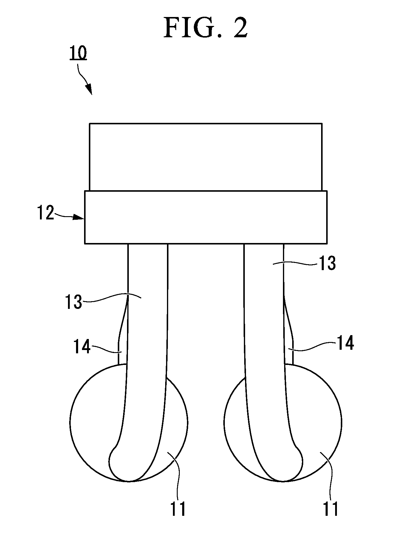
[0051]Hereinbelow, exemplary embodiments of the present invention shall be described with reference to the drawings. First, the constitution of a phase change cooler according to a first exemplary embodiment of the present invention shall be explained. FIGS. 1 to 3 show the constitution of a phase change cooler 10 of the present exemplary embodiment. FIG. 1 is an outline perspective view of the phase change cooler 10. FIG. 2 is an outline plan view of the phase change cooler 10 shown in FIG. 1. FIG. 3 is an outline front elevation of the phase change cooler 10 shown in FIG. 1.

[0052]FIG. 1 shows the phase change cooler 10 according to the first exemplary embodiment of the present invention that has two heat receiving units 11 and one heat radiating unit 12.

[0053]As shown in FIGS. 4 and 5, an electronic part D provided on a substrate K is installed below the heat receiving unit 11 via thermally conductive grease, a heat radiation sheet, and the like. In order to maintain a thermal con...

second exemplary embodiment

[0070]Next, a phase change cooler 20 according to a second exemplary embodiment of the present invention shall be described. As shown in FIG. 14A and FIG. 14B, in the phase change cooler 20, a bypass tube 21 that mutually connects the heat radiating units 11 is provided in order to maintain the supply capability of the refrigerant R to the heat receiving units 11. There is a great possibility of the amount of heat generation changing with the working ratio of the heat generating electronic part D in an electronic device. By providing the bypass tube 21, in the case of the working ratio of one electronic part D being in a high state, the liquid is supplied not only from the liquid tube 14, but also from the adjacent heat receiving unit 11.

[0071]When the bypass tube 21 is connected so as to directly connect a plurality of heat receiving units 11 in this way, the supply capability of the liquid phase refrigerant R improves, and it is possible to maintain a good cooling performance even...

third exemplary embodiment

[0072]Next, a phase change cooler 30 according to a third exemplary embodiment of the present invention shall be described. As shown in FIG. 15, in the phase change cooler 30, the respective lengths of the vapor tube 13 and the liquid tubes 14 differ for each heat receiving unit 11. In electronic devices and the like in which the phase change cooler 30 according to the exemplary embodiment of the present invention is applied, with regard to the installation position of the heat generating electronic part D, requirements from the perspective other than cooling such as electricity are also important. In the case where the positions of the electronic parts D and the heat radiation position are determined, and the distance between each heat receiving unit 11 and the heat radiating unit 12 differs, by extending the vapor tube 13 and the liquid tube 14 as needed, it is possible to maintain the cooling performance. Also, use in conjunction with the bypass tube 21 of the second exemplary em...


PUM


Abstract

A phase change cooler of the present invention includes: a plurality of heat receiving units that cause a refrigerant to change phase from liquid to gas by heat received from a heat generating body; one heat radiating unit that causes the refrigerant to change phase from gas to liquid by radiating heat to surrounding area; a plurality of vapor tubes that respectively transport the refrigerant in a vapor state from each of the heat receiving units to the heat radiating unit; a liquid tube that respectively circulates the refrigerant in a liquid state from the heat radiating unit to each of the heat receiving units; and a bypass tube that connects each of the heat receiving units to each other.

Description

TECHNICAL FIELD[0001]The present invention relates to cooling of a semiconductor device and electronic equipment. The present invention in particular relates to a semiconductor cooling device that circulates a refrigerant by utilizing the phase change phenomenon and electronic equipment that includes this device.BACKGROUND ART[0002]In order to convey a large quantity of heat that is generated in a semiconductor or electronic equipment, a method has been developed to obtain a high cooling performance by bonding a material having a high heat conductivity to the outer unit of a semiconductor, and flowing a refrigerant through the inside thereof as a heat absorber. A method has also been developed that obtains a higher cooling effect by boiling the refrigerant with the heat absorber. In order to dissipate the heat that the refrigerant has snatched to the outside, it is necessary to cause the refrigerant to circulate between the heat absorbing unit and a heat radiating unit. Generally, a...

Claims


Application Information

Patent Timeline
Patent Type & Authority Applications(United States)
IPC IPC(8): F28D15/02
CPCF28D15/0266H01L23/427H01L23/467H01L2924/0002H01L2924/00
Inventor SAKAMOTO, HITOSHIYOSHIKAWA, MINORUINABA, KENICHIHASHIGUCHI, TAKEYA
Owner NEC CORP
Why Eureka
Try Eureka