Oxygen separation assembly and method

Inactive Publication Date: 2010-05-13
PRAXAIR TECH INC
View PDF11 Cites 30 Cited by
  • Summary
  • Abstract
  • Description
  • Claims
  • Application Information

AI Technical Summary

Benefits of technology

[0010]The division of the electrical current allows the electrical current to be more evenly distributed throughout the tubular membrane element to prevent hot spots from developing and leading to

Problems solved by technology

However, since there is no cathode layer and as will be discussed, also possibly no anode layer there is no electrical c

Method used


Image

  • Oxygen separation assembly and method
  • Oxygen separation assembly and method
  • Oxygen separation assembly and method

Examples


Embodiment Construction

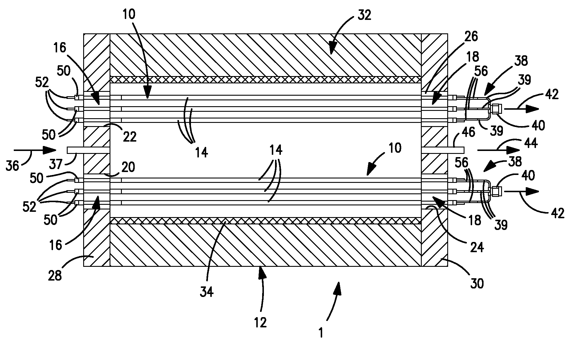
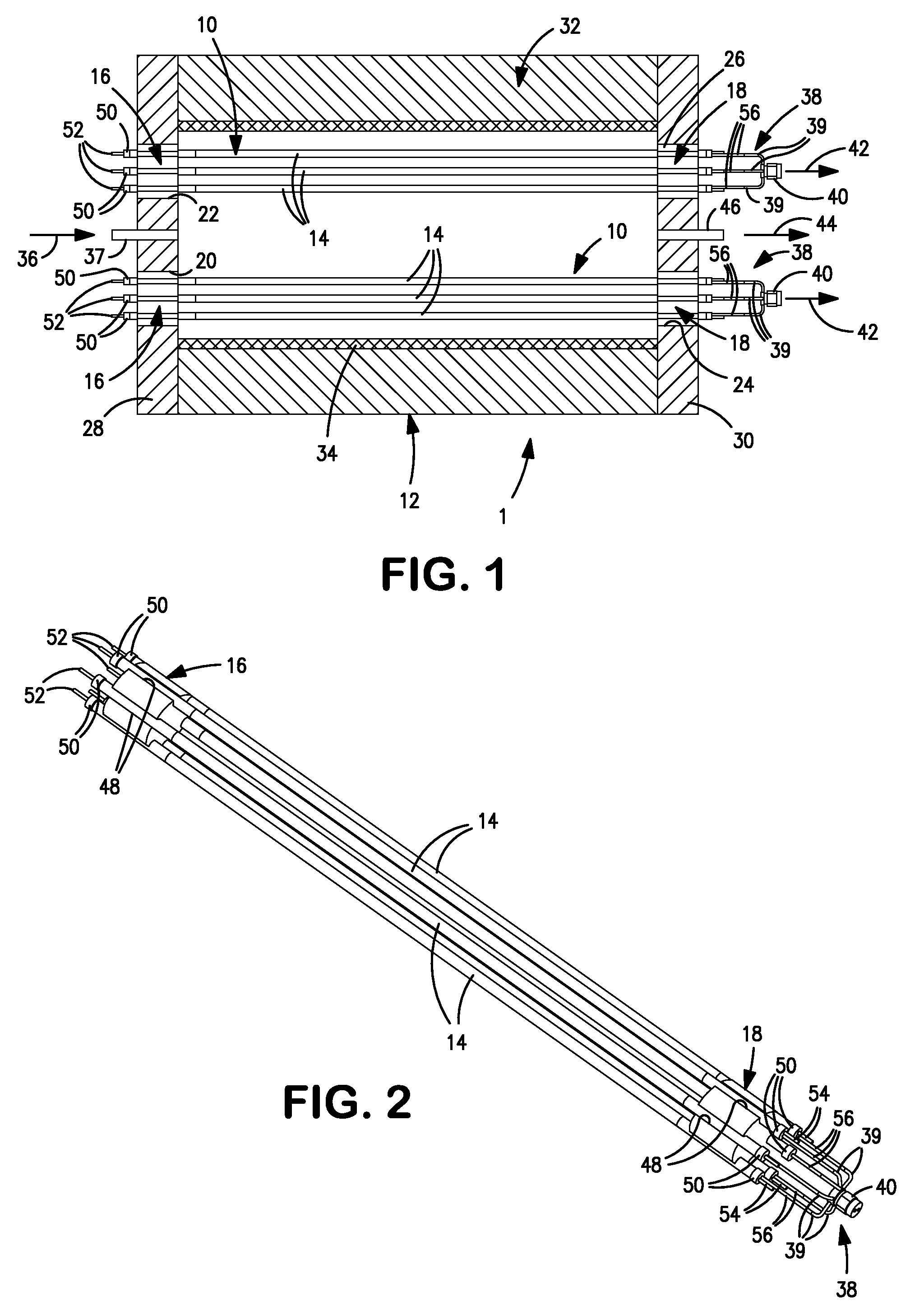
[0026]With reference to FIG. 1, an oxygen separator 1 is illustrated that has oxygen separation assemblies 10 housed within a heated containment 12. Oxygen separation assemblies 10 are each formed by tubular membrane elements 14 that are held in a bundle-like position by end insulation members 16 and 18 that are fabricated from high purity alumina fiber. The tubular membrane elements for exemplary purposes can have an outer diameter of about 6.35 mm., a total wall thickness of about 0.5 mm. and a length of about 55 cm. The end insulation members 16 and 18 are retained within opposite openings 20, 22 and 24 and 26 defined in insulated end walls 28 and 30 of heated containment 12. Heated containment 12 can be of cylindrical configuration having an insulated sidewall 32 connecting the end walls 28 and 30. A heated insulation layer 34 is coaxially positioned within insulated sidewall 32 and contains heating elements to heat the tubular membrane elements 14 to an operational temperature ...


PUM


Abstract

The present invention provides an electrically driven oxygen separation assembly and method of applying an electrical potential thereto in which one or more tubular membrane elements are provided having an anode layer, a cathode layer, an electrolyte layer and two current collector layers adjacent to and in contact with the anode layer and the cathode layer and situated on the inside and outside of the at least one tubular membrane element. The potential is applied to one of the two current collector layers at two central spaced locations of the at least one tubular membrane element and to the other of the two current collector layers at least at opposite end locations thereof. As a result the electric current flow through the tubular membrane element is divided into two parts flowing between the two central spaced locations and the opposite end locations.

Description

FIELD OF THE INVENTION[0001]The present invention relates to an electrically driven oxygen separation assembly and method in which the oxygen is separated with the use of one or more tubular membrane elements of the assembly. More particularly the present invention relates to such an oxygen separation assembly and method in which the electrical potential is applied at opposed electrodes of the tubular membrane element or elements at two central spaced locations and at least at two end locations of the tubular membrane element outwardly spaced from the two central spaced locations.BACKGROUND OF THE INVENTION[0002]Electrically driven oxygen separators are used to separate oxygen from oxygen containing feed, for example, air. Additionally, such devices are also used in purification application where it is desired to purify an oxygen containing feed by separating oxygen from the feed. Electrically driven oxygen separators can utilize tubular membrane elements having a layered structure ...

Claims


Application Information

Patent Timeline
IPC IPC(8): B03C3/06
CPCB01D53/326B01D2053/223B01D2256/12B01D2257/104B01D2258/06C01B13/0255C01B2210/0046
Inventor REED, DAVID M.SUGGS, DAVIDCOLLINS, MICHAEL J.KELLY, RICHARDCHRISTIE, GERVASE M.
Owner PRAXAIR TECH INC
Why Eureka
Try Eureka