Submerged Substrate Plug Cutter and Related Method

a technology of submerged substrate and plug cutter, which is applied in the field of submerged substrate plug cutter and related method, can solve the problems of ineffective and physically demanding methods, many physical and practical challenges of seagrass habitat establishment, and the difficulty of establishing seagrass habitat using these methods,

Inactive Publication Date: 2010-05-13
STANTEC CONSULTING SERVICES
View PDF2 Cites 13 Cited by
  • Summary
  • Abstract
  • Description
  • Claims
  • Application Information

AI Technical Summary

Benefits of technology

[0015]The present invention includes a manually operated plug cutter, a transport receptacle to be used in conjunction with the cutting device, and a related method for collecting and transporting plugs of submerged aquatic vegetation or submerged substrate core samples and further transplanting the collected submerged aquatic vegetation (typically, plugs of seagrass) along with the associated sediment. The method integrates the sequential collection, transport, and planting of submerged aquatic vegetation plug or the collection and transport of a submerged substrate core sample. During the collection process the plug cutter utilizes a hollow cutting member with a sharpened serrated bottom edge. Further, a ball-valve assembly, constructed of non-corrosive material, along with a rubber gasket and cap set on top of the hollow cutting member are utilized to create vacuum pressure inside the hollow cutting member, which is necessary to remove the submerged aquatic vegetation plug or submerged substrate core sample from the submerged substrate. A handle attached to the hollow cutting member is used to drive the hollow cutting member into the submerged substrate and, eventually, to help lift the plug cutter out of the submerged substrate. Optionally, an attached plate surrounding the hollow cutting member serves as a handle, a foot operated means of inserting the plug cutter into the submerged substrate, and a depth guide for the collection of the submerged aquatic vegetation plugs or submerged substrate core sample. The plug cutter also uses compressed air to release the vacuum pressure between the hollow cutting member and the submerged substrate. The collected unit is then transferred to the corresponding transport receptacle by placing the plug cutter on top of the transport receptacle and opening the ball-valve to release the vacuum pressure inside the hollow cutting member allowing the collected plug to slide into the transport receptacle. Following the transfer of a submerged aquatic vegetation plug to a recipient site, the plug cutter is utilized to create a hole in which the collected submerged aquatic vegetation plug is installed flush with the adjacent substrate by holding the transport receptacle over the hole and removing the transport receptacle's removable bottom to allow the collected plug to be installed into the hole.

Problems solved by technology

Whether it is for the purpose of restoring impacted seagrass beds or establishing new areas of seagrasses, the transplantation of seagrasses presents many physical and practical challenges to those who engage in this important activity.
Although different techniques of hand planting seagrasses have been historically employed by others, such as the peat pot method, staple method, and plug method (A Guide to Planting Seagrasses in the Gulf of Mexico, Fonseca), establishment of seagrass habitat using these methods has historically been problematic, particularly when transplanting relatively large areas of seagrass.
In addition to varying degrees of success with these planting methods, these methods have also proven to be inefficient and physically demanding for those implementing them.
While relatively efficient, this method removes a limited amount of associated sediment with the cut seagrass plug, which makes it susceptible to failure when transplanted in recipient areas with high wave energy and / or current velocities.
The staple method addresses some of the concerns about high wave energy / current velocity, but the method involves the time-consuming step of attaching the seagrass plants to staples before they are transplanted.
Further, this method may result in the undesirable side effect of leaving potentially sharp pieces of partially-oxidized metal staples in the bottom of the recipient area.
(1971) and U.S. Pat. No. 5,492,181 to Grant (1994) each disclose devices to be used for cutting and planting plugs of turf or sod, which while addressing the cutting of substrate do not allow for the efficient cutting of a submerged unit, including the removal of a submerged aquatic vegetation unit without damaging the unit, nor do they describe any means for transporting the removed plug outside of the device.
U.S. Pat. No. 4,282,684 to McLellan (1981) discloses a plant transplanter which provides for a device with cuts into the substrate to remove a plant for transplanting, but does not make any provisions for creating vacuum pressure in the cylindrical member to allow for efficient cutting and transplanting of submerged aquatic plants.
Also, U.S. Pat. No. 4,135,752 to Long (1979) discloses a ground plugging device which combines a tubular metal body with teeth on the bottom edge and a blunt edge on top for accepting foot pressure; however, it does not address preserving the cut plug for purposes of transplanting nor does it address the problem of efficiently removing a plug of submerged substrate.
U.S. Pat. No. 6,070,537 to Anderson (2000) discloses a process and apparatus for planting shoots of nursery-incubated aquatic plants, but does not provide for the effective cutting and subsequent transplanting of existing viable seagrass plugs from a donor bed to a recipient site.
In addition, U.S. Pat. No. 6,684,536 to Anderson (2004) discloses a planter for a slab of seagrass and related process, which provides a means for cutting a large quantity of seagrass for the purpose of transplanting; however, cutting of seagrasses in a slab, as opposed to smaller more manageable plugs as provided for in the subject invention, is often not a viable option based on the conditions at the donor bed or recipient site.

Method used


Image

  • Submerged Substrate Plug Cutter and Related Method
  • Submerged Substrate Plug Cutter and Related Method
  • Submerged Substrate Plug Cutter and Related Method

Examples


Embodiment Construction

[0025]Plug Cutter

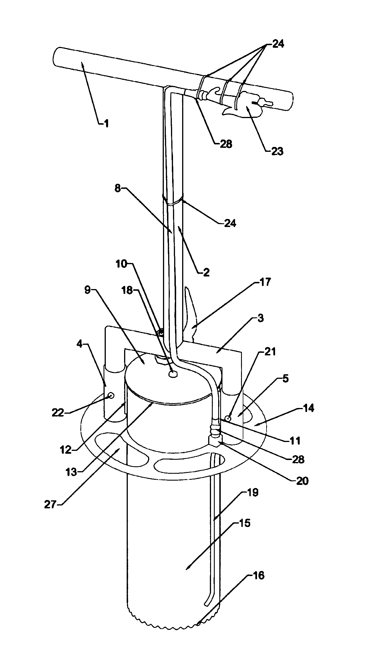
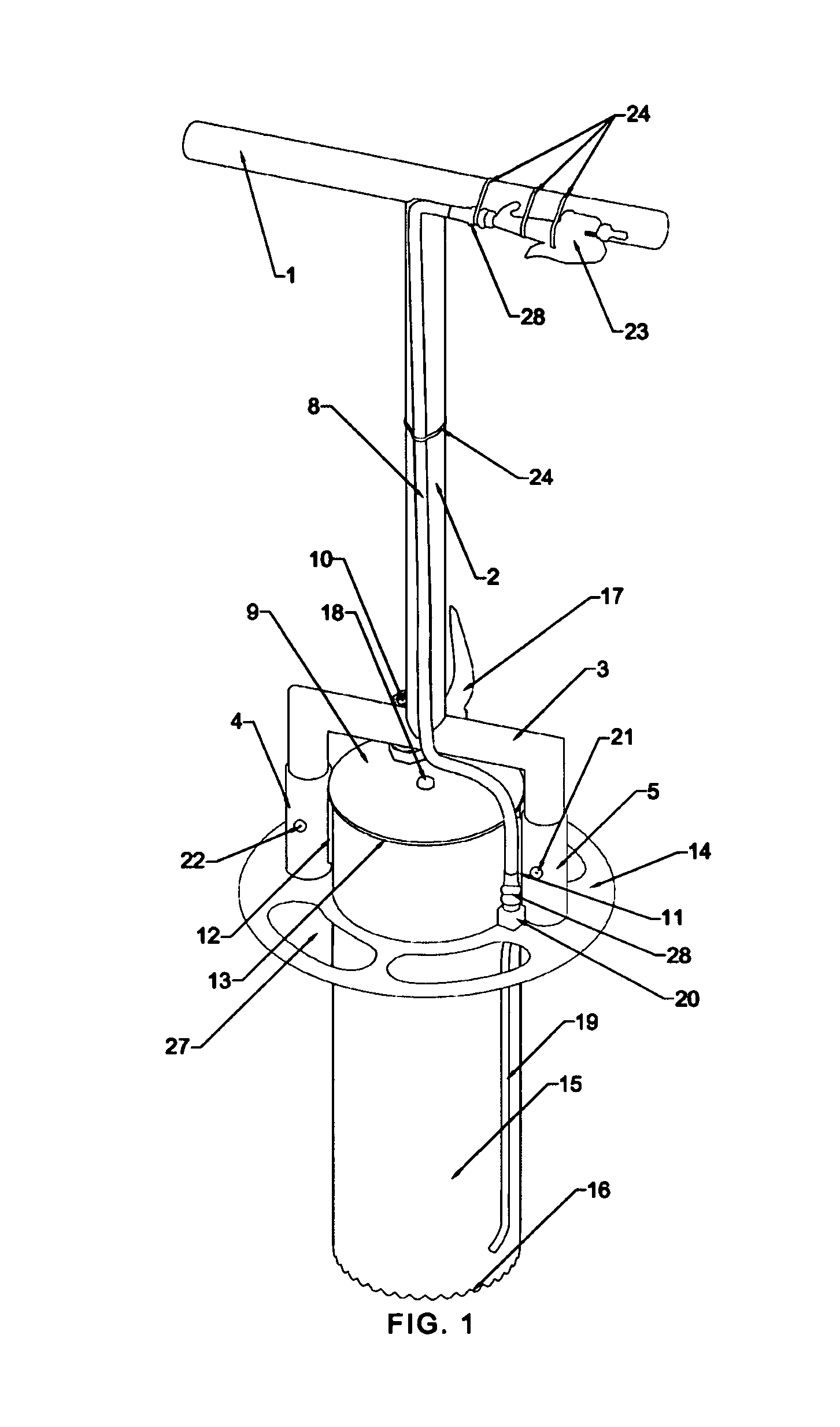
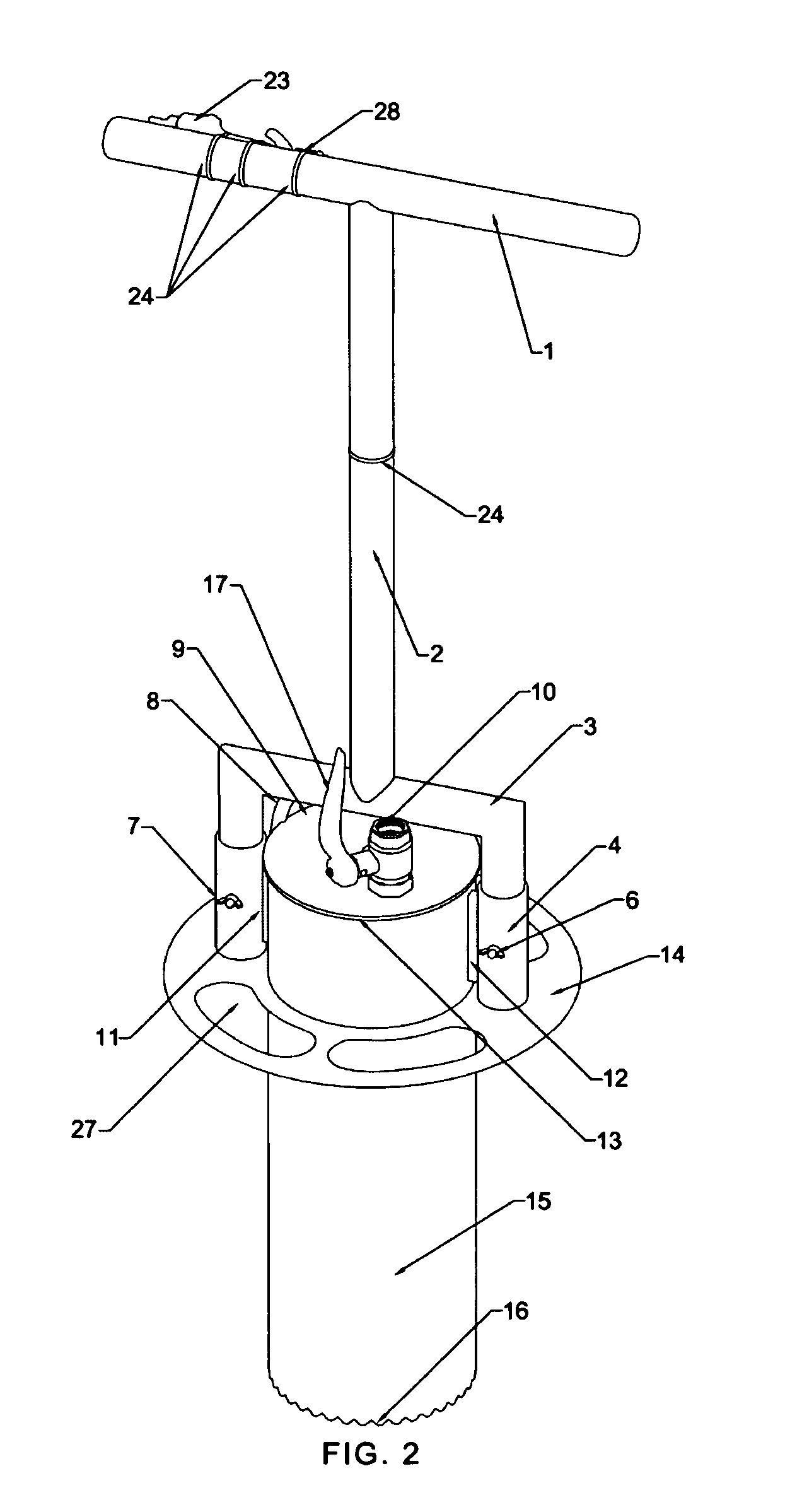
[0026]Referring now to the drawings, wherein like reference characters designate like or corresponding parts throughout the several views, there is shown in FIGS. 1 and 2 the preferred embodiment of the plug cutter. Unless otherwise noted, the components of the plug cutter are to be constructed of a durable, light-weight, and non-corrosive material such as stainless steel.

[0027]The hollow cutting member 15 is open at both ends and has sharpened serrated cutting teeth 16 along the bottom edge to allow for easier penetration of the submerged substrate. In addition, this design will allow for the clean shearing of the targeted plant (including the plant's root system or rhizomes) to assist with the preservation of the targeted plant and surrounding substrate during transportation and transplant. In the preferred embodiment, the hollow cutting member 15 is cylindrical and designed with an approximate length of 35.6 cm (14 inches) and an approximate outside diameter of 1...


PUM


Abstract

A device for use in cutting plugs of submerged substrate and particularly seagrass plugs for the purpose of transplanting using a corresponding transport receptacle and method. The device utilizes a hollow cutting member with a serrated bottom edge capable of being placed over a targeted area and forced into the submerged substrate, created vacuum pressure in the hollow cutting member, and compressed air injected between the exterior of the hollow cutting member and the submerged substrate to accomplish cutting of a submerged substrate unit. Vacuum pressure in the hollow cutting member is released to transfer the collected unit to the corresponding transport receptacle with a removable bottom. A corresponding method for transplanting a collected seagrass plug is further accomplished by creating a hole at recipient site using the device and removing the transport receptacle's removable bottom to release the plug into the created hole.

Description

CROSS-REFERENCE TO RELATED APPLICATIONS[0001]This application is related to provisional patent application Ser. No. 60 / 950,169 filed Jul. 17, 2007, and claims the benefit of this earlier filing date.STATEMENT REGARDING FEDERALLY SPONSORED RESEARCH OR DEVELOPMENT[0002]Not ApplicableTHE NAMES OF THE PARTIES TO A JOINT RESEARCH AGREEMENT[0003]Not ApplicableINCORPORATION-BY-REFERENCE OF MATERIAL SUBMITTED ON A COMPACT DISC[0004]Not ApplicableBACKGROUND OF THE INVENTION[0005]1. Field of the Invention[0006]This invention relates to devices and methods used for cutting plugs of submerged substrate and, more particularly, a device and corresponding method used for cutting plugs of submerged aquatic vegetation (seagrass), a corresponding receptacle for transporting the cut plug, and a related method for transplanting a submerged aquatic vegetation plug.[0007]2. Description of Related Art[0008]The present invention provides an improved method and device for collecting, transporting, and trans...

Claims


Application Information

Patent Timeline
Patent Type & Authority Applications(United States)
IPC IPC(8): A01C5/02A01C11/00A01B1/00E21B25/18
CPCA01C5/02A01C11/003Y10S111/90Y10S111/919
Inventor DENNIS, III, RAYMOND FRANKLINMONTIN, GARY JOEBURTON, MICHAEL ADAM GRANVILLEANDERSEN, GARY RAY
Owner STANTEC CONSULTING SERVICES
Why Eureka
Try Eureka