Power transmitting apparatus

a power transmission and power technology, applied in the direction of mechanical actuated clutches, electric propulsion mountings, gearing, etc., to achieve the effect of reducing nois

Inactive Publication Date: 2010-05-13
TOYOTA JIDOSHA KK
View PDF6 Cites 14 Cited by
  • Summary
  • Abstract
  • Description
  • Claims
  • Application Information

AI Technical Summary

Benefits of technology

[0004]According to the above power transmitting unit, a position of the clutch moving portion can be fixed when the clutch moving portion reaches the end of the movement stroke even if the excitation coil of the clutch driving portion is in a non-excitation state. However, outer diameters of the clutch moving portion and the clutch driving portion should be enlarged to some extent in order to

Problems solved by technology

Further, in a dog clutch driven by an electromagnetic actuator as described above, the challen

Method used


Image

  • Power transmitting apparatus
  • Power transmitting apparatus
  • Power transmitting apparatus

Examples


Embodiment Construction

[0033]One mode of carrying out the invention is discussed below as a preferred embodiment.

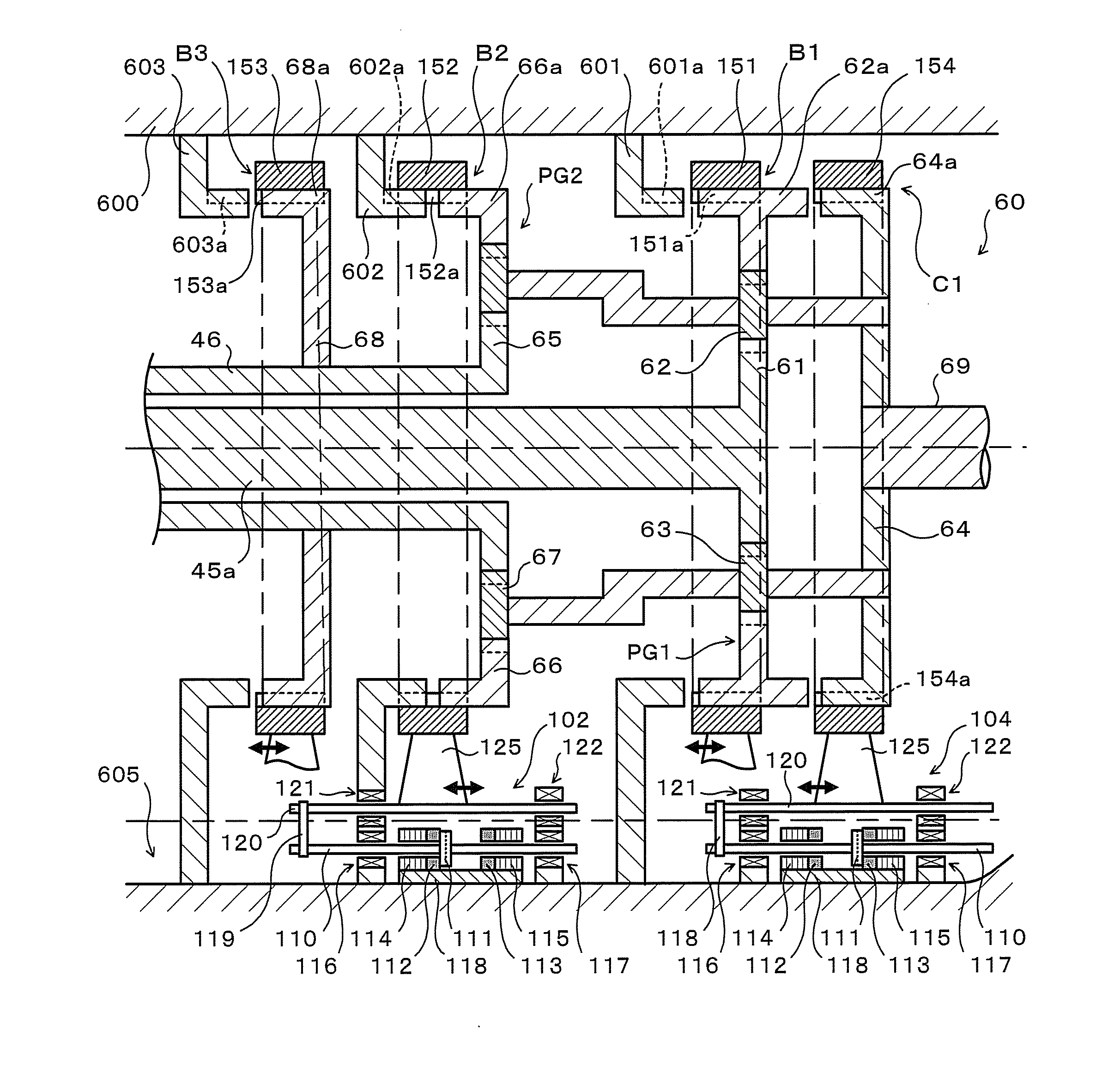
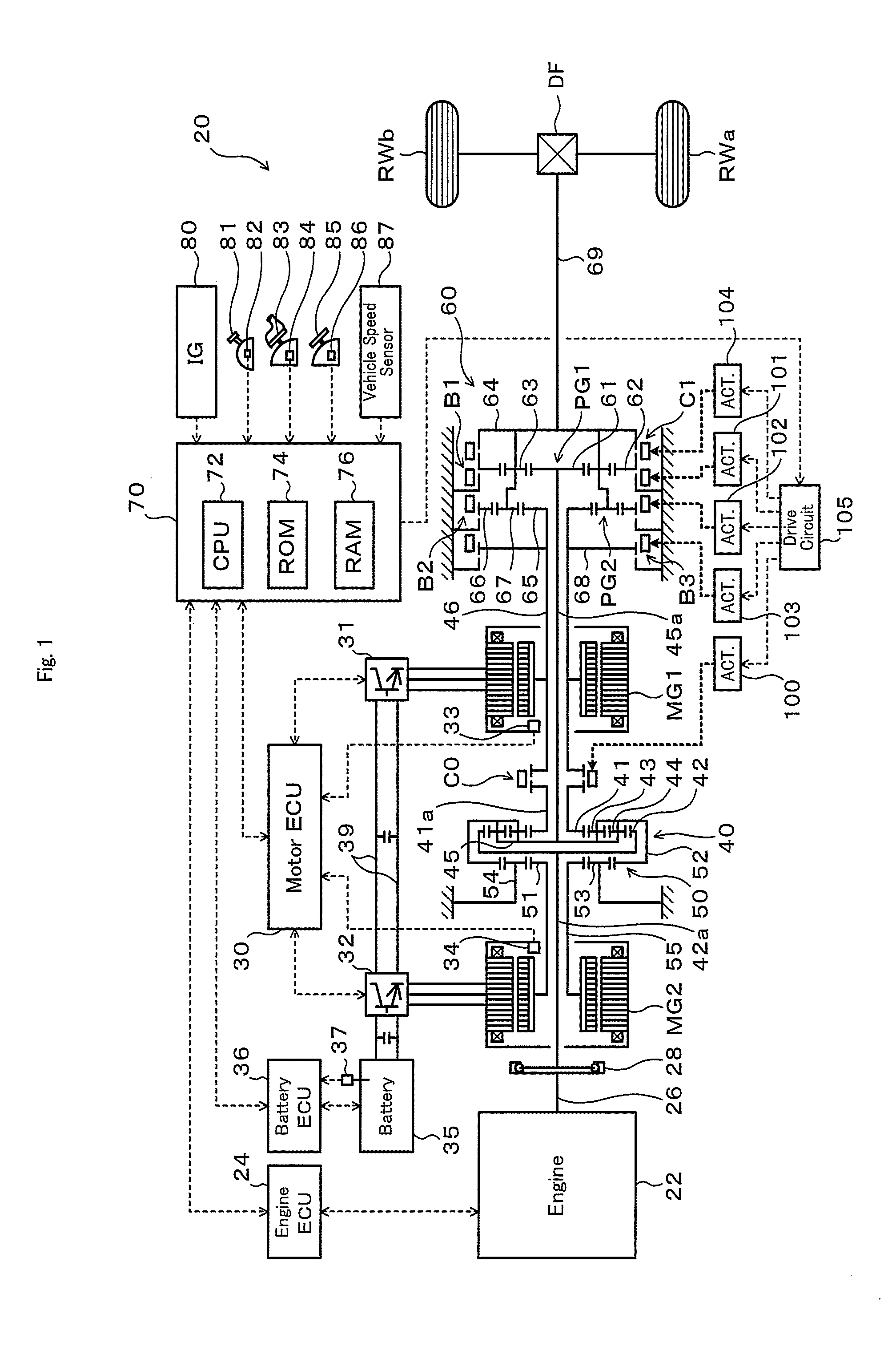
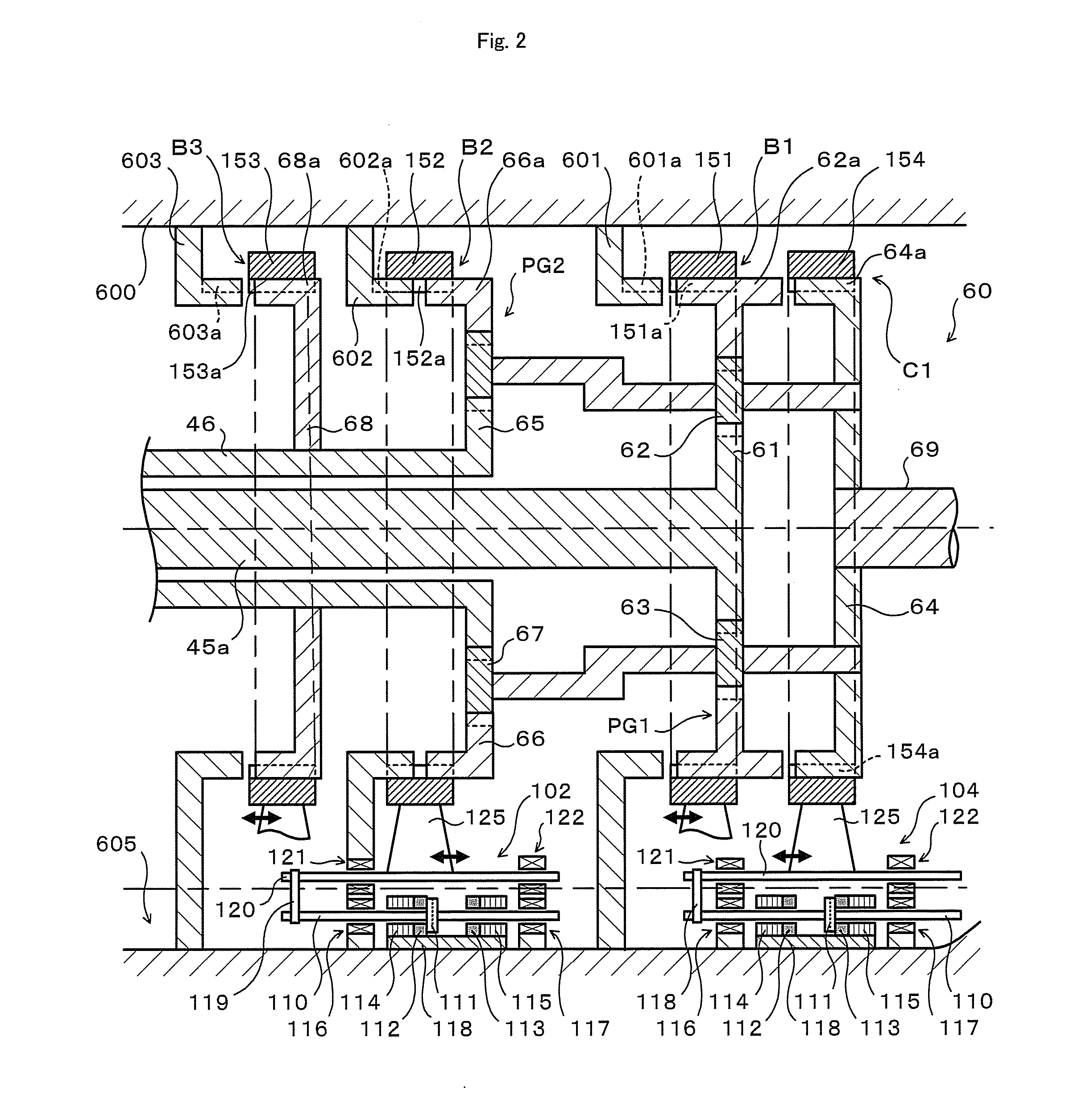
[0034]FIG. 1 is a schematic block diagram of a hybrid vehicle 20 including a transmission 60 that is a power transmitting apparatus according to one embodiment of the invention. The hybrid vehicle 20 shown in FIG. 1 is constructed as, for example, a rear-wheel drive vehicle and includes an engine 22 located in a front portion of the vehicle body, a power distribution integration mechanism 40 connected to a crankshaft (engine shaft) 26 of the engine 22, a motor MG1 having power generation capability and linked with the power distribution integration mechanism 40, a motor MG2 having power generation capability and linked with the power distribution integration mechanism 40 via a reduction gear mechanism 50 to be coaxial with the motor MG1, a transmission 60 that transmits power from the power distribution integration mechanism 40 to a driveshaft while changing a rotational speed, and a hybrid ele...


PUM


Abstract

A transmission includes a transmission case, an oil pan that is defined in a lower portion within the transmission case and stores a lubricating medium capable at least of lubricating components of the transmission, movable engagement members capable of engaging with two elements that respectively correspond thereto, and electromagnetic actuators that respectively move a corresponding one of the movable engagement members to allow a connection between the two elements and a release of the connection.

Description

TECHNICAL FIELD[0001]The present invention relates to a power transmitting apparatus that has a plurality of elements including at least two rotating elements and is capable of transmitting power between the two rotating elements.BACKGROUND ART[0002]There is known a conventional two-speed power transmitting unit for an electric scooter as an electric vehicle, that includes a dog clutch having a cylindrical clutch moving portion on which a permanent magnet is mounted and a cylindrical clutch driving portion on which an excitation coil is mounted, and an excitation circuit that reverses an acting force in response to a movement of the clutch moving portion by excitation of the clutch driving portion (see, Patent Document 1). In the power transmitting unit, thicknesses in both ends of a yoke of the clutch driving portion are larger than those in both ends of a yoke of the clutch moving portion. Accordingly, an attraction force acts between the permanent magnet of the clutch moving port...

Claims


Application Information

Patent Timeline
IPC IPC(8): F16D27/01F16D27/00
CPCB60K1/02F16H2063/305B60K6/387B60K6/445B60K6/547B60L2240/421B60L2240/486B60W10/02B60W10/06B60W10/08B60W10/115B60W20/00B60W2510/081B60W2510/1005B60W2510/246B60W2540/10B60W2540/12F16H3/728F16H63/304F16H2037/0866F16H2061/6603F16H2200/2012F16H2200/2043F16H2200/2064F16H2200/2097Y02T10/56Y02T10/6239Y02T10/6286Y02T10/642B60W10/30B60W20/10B60K6/365B60W2050/0031B60W2510/244Y02T10/62Y02T10/64Y02T10/40
Inventor OBA, HIDEHIROKIMURA, HIROMICHI
Owner TOYOTA JIDOSHA KK
Why Eureka
Try Eureka