Three phase electrocoagulation effluent treatment apparatus and methods

a technology of effluent treatment and electrocoagulation, applied in multi-stage water/sewage treatment, water/sewage treatment by degassing, water/sewage treatment water nature, etc., can solve the problems of large floor space, not all effluent treatment requires the same technology, and affects ongoing operations financially and operational continuity. , to achieve the effect of enhancing equipment and plant efficiency and reliability, reducing maintenance and plant floor space requirements

Inactive Publication Date: 2010-05-13
ROCKWATER RESOURCE
View PDF26 Cites 18 Cited by
  • Summary
  • Abstract
  • Description
  • Claims
  • Application Information

AI Technical Summary

Benefits of technology

[0006]This invention provides three phase electrocoagulation effluent treatment apparatus and methods that reduce maintenance and plant floor space requirements and that enhance equipment and plant efficiency and reliability. The three phase separation method employs three integrated removal areas in an electrocoagulation reactor In phase one, light flotation solids in the floc-foam, gas (H2 and O2), and oil and grease layers are separated at the liquid surface and removed by an adjustable vacuum. In phase two, the semi-clarified effluent of the primary electrocoagulation treated water is separated from underneath the floc-foam surface layer at a primary chamber and is either transferred into secondary electrocoagulation reactor chambers or discharged, for example into a settling tank. In phase three, the solids precipitate out into integrated electrocoagulation sludge chamber, thereat proceeding through the normal sedimentation process mechanics before discharge.
[0011]It is another object of this invention to provide electrocoagulation effluent treatment apparatus that are efficient and reliable.

Problems solved by technology

Such facilities typically represent a significant investment by the business / community, and the performance of the facility (or failure thereof) can seriously impact ongoing operations financially and in terms of operational continuity.
Moreover, not all effluent treatment requires the same technologies.
However, apparatus for performing such processes have heretofore required extensive maintenance and investment to assure proper operations, and have required extensive floor space for their installation.
Moreover, some heretofore known apparatus have been inefficiently designed affecting both overall operation of the apparatus and plant as well as apparatus longevity.
Present electrocoagulation art does not adequately address the mechanisms of flotation, sedimentation and the circulation effect of coagulant aggregation in the early stages as bridging flocs.

Method used


Image

  • Three phase electrocoagulation effluent treatment apparatus and methods
  • Three phase electrocoagulation effluent treatment apparatus and methods
  • Three phase electrocoagulation effluent treatment apparatus and methods

Examples


Embodiment Construction

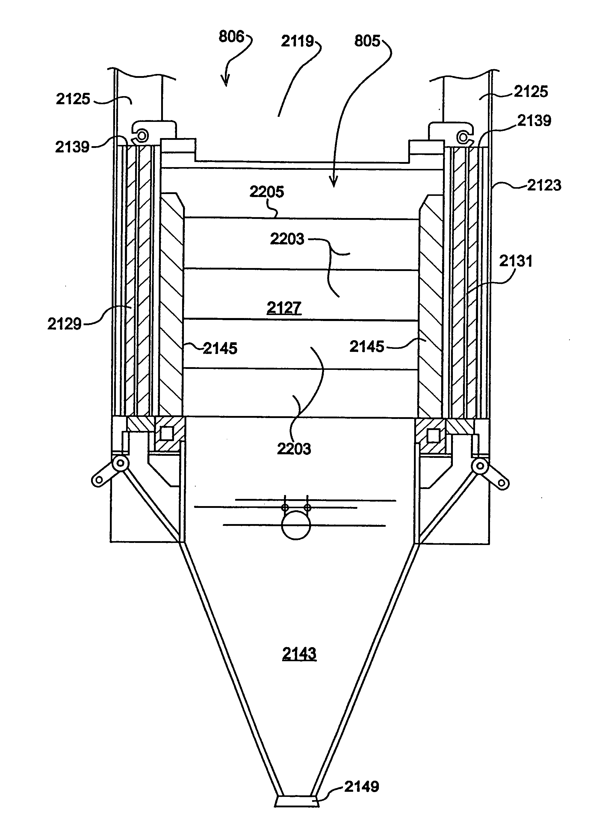
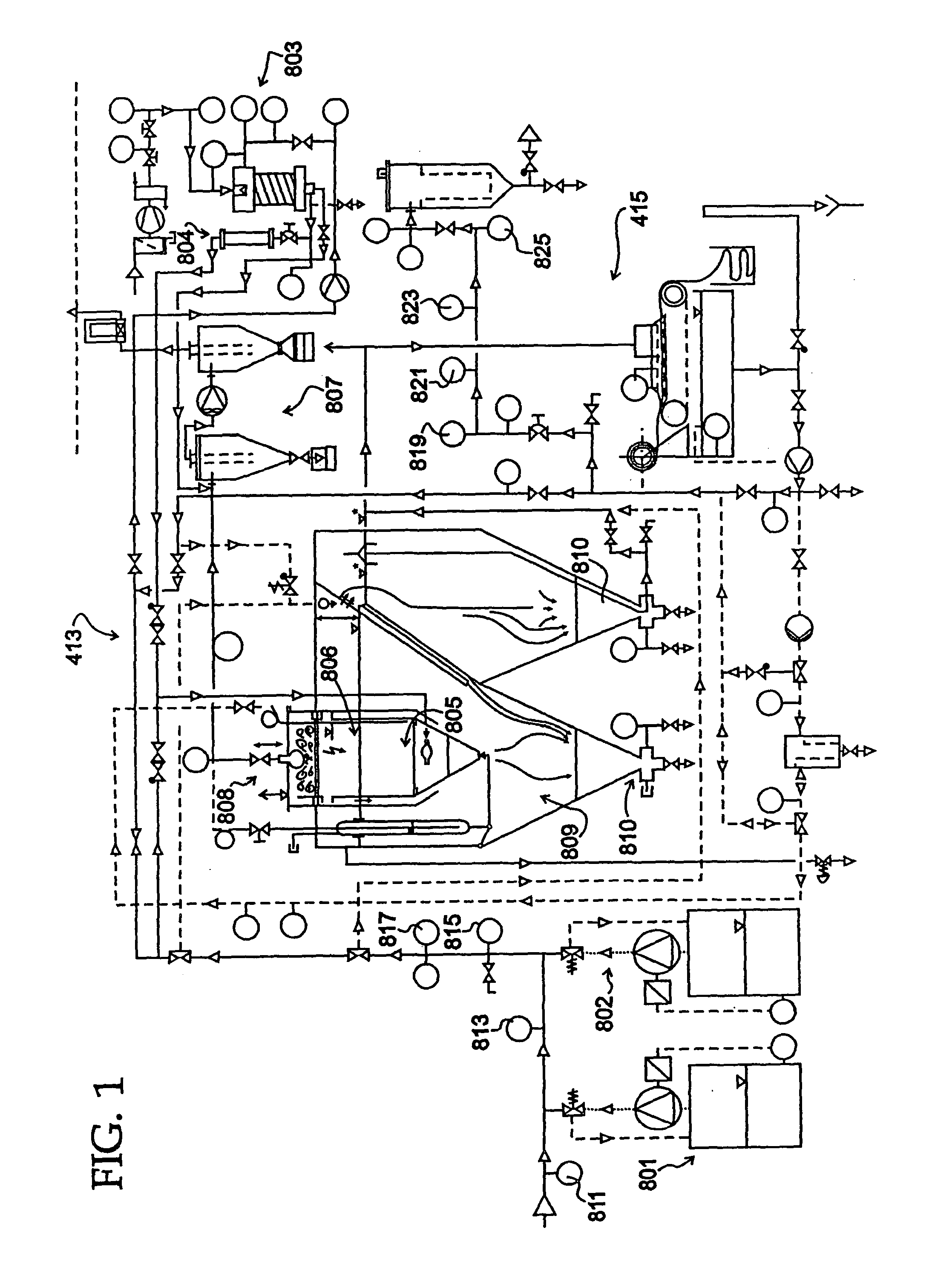
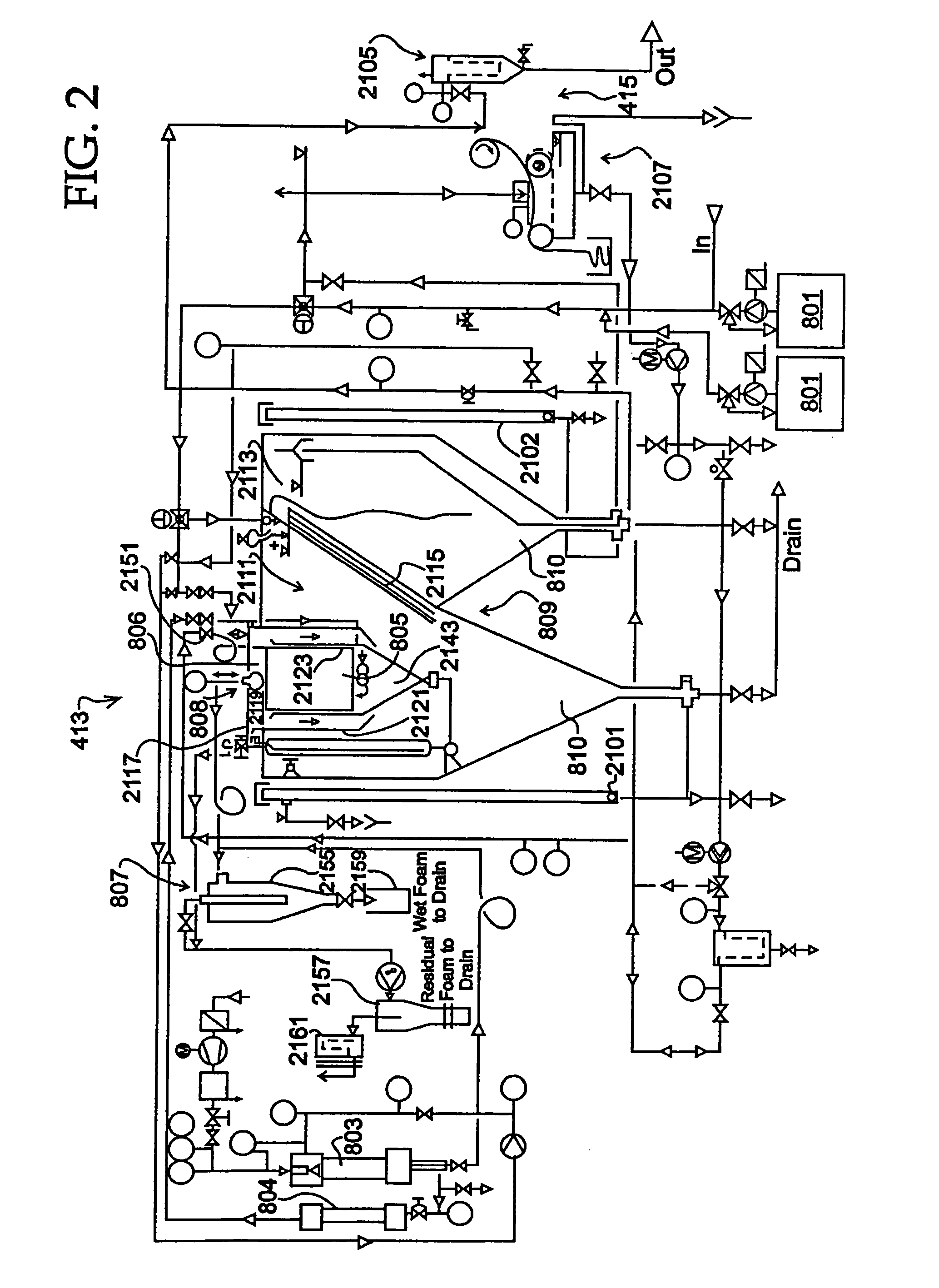
[0022]FIG. 1 shows effluent treatment apparatus (in this case a pre-treatment suite) 413. These include pH and chemical dosing apparatus 801 and 802, respectively, ODE / IDI membrane aeration apparatus 803, electrocoagulation apparatus 805, dissolved air / gas flotation 806, vacuum introduced cyclone separation apparatus 807, vacuum degassing 808, lamella plate clarification 809 and sludge concentration output 810. Additionally, eight testing nodes 811 through 825 are shown.

[0023]The primary function of pre-treatment suite 413 is the removal or significant reduction (exceeding 90%) of colloidal matter with total suspended solids, such as polysaccharides or other slimy matter, less than about 75 nm. In addition, removal or significant reduction (by 80 to 90%) of fats, grease, oils and emulsions, and heavy metals (such as barium, strontium and others) by 60 to 99% is achievable. Finally, removal of entrained and produced gas by vacuum down to residual levels is achieved.

[0024]Regarding bo...


PUM

PropertyMeasurementUnit
chamber angle of reposeaaaaaaaaaa
frequencyaaaaaaaaaa
lengthaaaaaaaaaa

Abstract

Electrocoagulation effluent treatment apparatus and methods are disclosed, the apparatus including a primary electrocoagulation reactor chamber having treatment electrodes maintained therein and an effluent inlet and treated effluent outlet. An integrated flotation chamber is located above the reaction chamber, a vacuum device connectable with a vacuum source being received in the flotation chamber and including a foam intake and an output. A sludge chamber is defined below and integrated with the primary reaction chamber and has a settled sludge output.

Description

FIELD OF THE INVENTION[0001]This invention relates to effluent treatment, and, more particularly, relates to electrocoagulation treatment systems and methods for effluent treatment.BACKGROUND OF THE INVENTION[0002]Most industrial and municipal processes require water treatment facilities to treat effluents returned to the environment. Such facilities typically represent a significant investment by the business / community, and the performance of the facility (or failure thereof) can seriously impact ongoing operations financially and in terms of operational continuity.[0003]Moreover, not all effluent treatment requires the same technologies. Industrial effluents (such as is found at coal bed methane facilities or oil production sites, for example) all have different particulate, pollutant and / or biomass content inherent to both the industrial processes as well as the particular water and soil conditions found at the site. Municipal requirements would likewise vary depending on desired...

Claims


Application Information

Patent Timeline
Patent Type & Authority Applications(United States)
IPC IPC(8): C02F1/463
CPCB01D61/022C02F2103/365B01D61/027C02F1/20C02F1/38C02F1/42C02F1/441C02F1/442C02F1/463C02F1/52C02F1/66C02F3/082C02F9/00C02F2001/007C02F2201/008C02F2209/00C02F2209/005C02F2209/006C02F2209/008B01D61/02B01D65/02Y02W10/15B01D19/0036B01D61/025Y02W10/10B01D61/026B01D61/029
Inventor WIEMERS, REGINALD A.KOHLHEB, ROBERT
Owner ROCKWATER RESOURCE
Why Eureka
Try Eureka