Trolling motor mount

a technology of trolling motors and mounting brackets, which is applied in the field of trolling motors, can solve the problems of insufficient dexterity or strength of anglers inability to eliminate the shortcomings of association, and inability to move the trolling motor

Inactive Publication Date: 2010-05-13
TODD WILLIAM J +1
View PDF25 Cites 19 Cited by
  • Summary
  • Abstract
  • Description
  • Claims
  • Application Information

AI Technical Summary

Benefits of technology

[0011]It is, therefore, an object of the present invention to provide a trolling motor mount that permits the operator to automatically deploy, stow, and secure the trolling motor when in use on the water.
[0012]It is another object to permit operators of any age, size, or physical condition to safely utilize a trolling motor mount.
[0013]It is another object to provide a trolling motor mount that is easy to install, operate, and maintain.
[0014]It is yet another object to initiate deployment and retraction of the trolling motor from any position on the boat without having to stand in close proximity to the motor mount.
[0016]And it is another object to provide a trolling motor mount that is easily installed as an aftermarket item for existing users.

Problems solved by technology

Several disadvantages are presented with such known bow mounts.
Thus, deploying or stowing the trolling motor typically requires more than one hand to pivot the arm assembly.
These mounting apparatuses also force the angler to reach and bend over on the edge of the boat to grab the rope handle, which is inconvenient, difficult, and sometimes dangerous, and some anglers may not have sufficient dexterity or strength to move the trolling motor between the deployed and stowed positions.
These disadvantages are amplified when fishing on open lakes and bays where breaking waves and gusting winds occur.
This mount, however, still fails to eliminate the shortcomings associate with convention bow mounts: the mount operator still must pull a rope handle to pivot the arm assembly, which in turn requires a certain degree of strength, exteriority, and attention.

Method used


Image

  • Trolling motor mount
  • Trolling motor mount
  • Trolling motor mount

Examples


Embodiment Construction

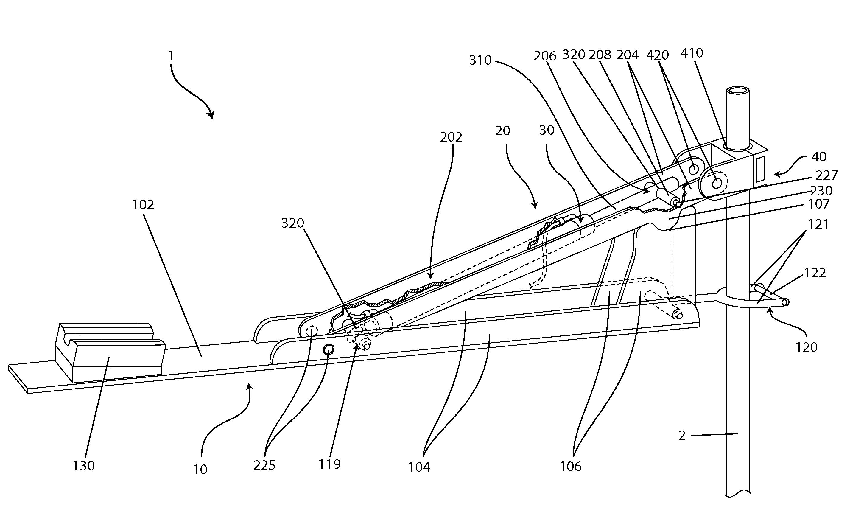
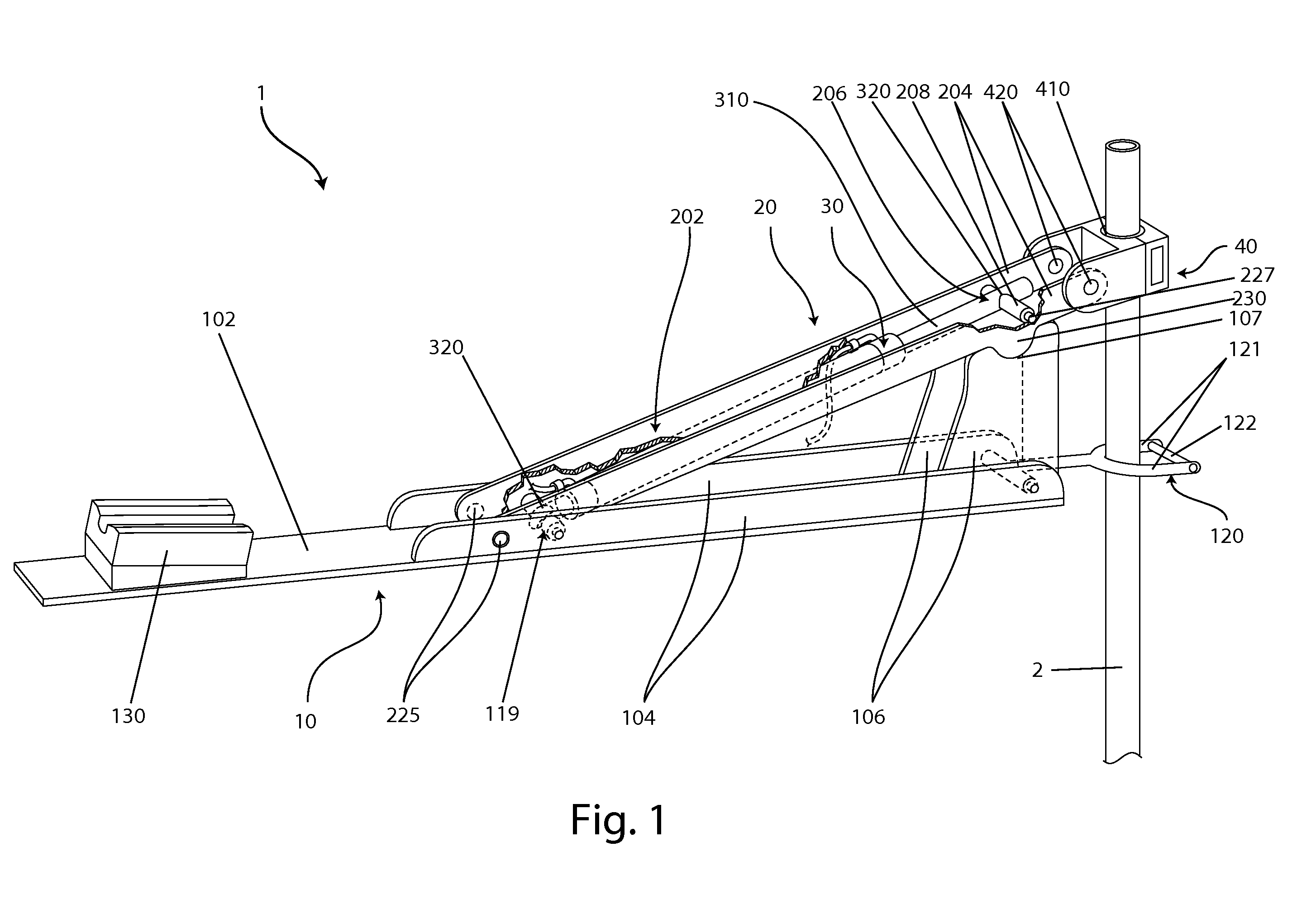
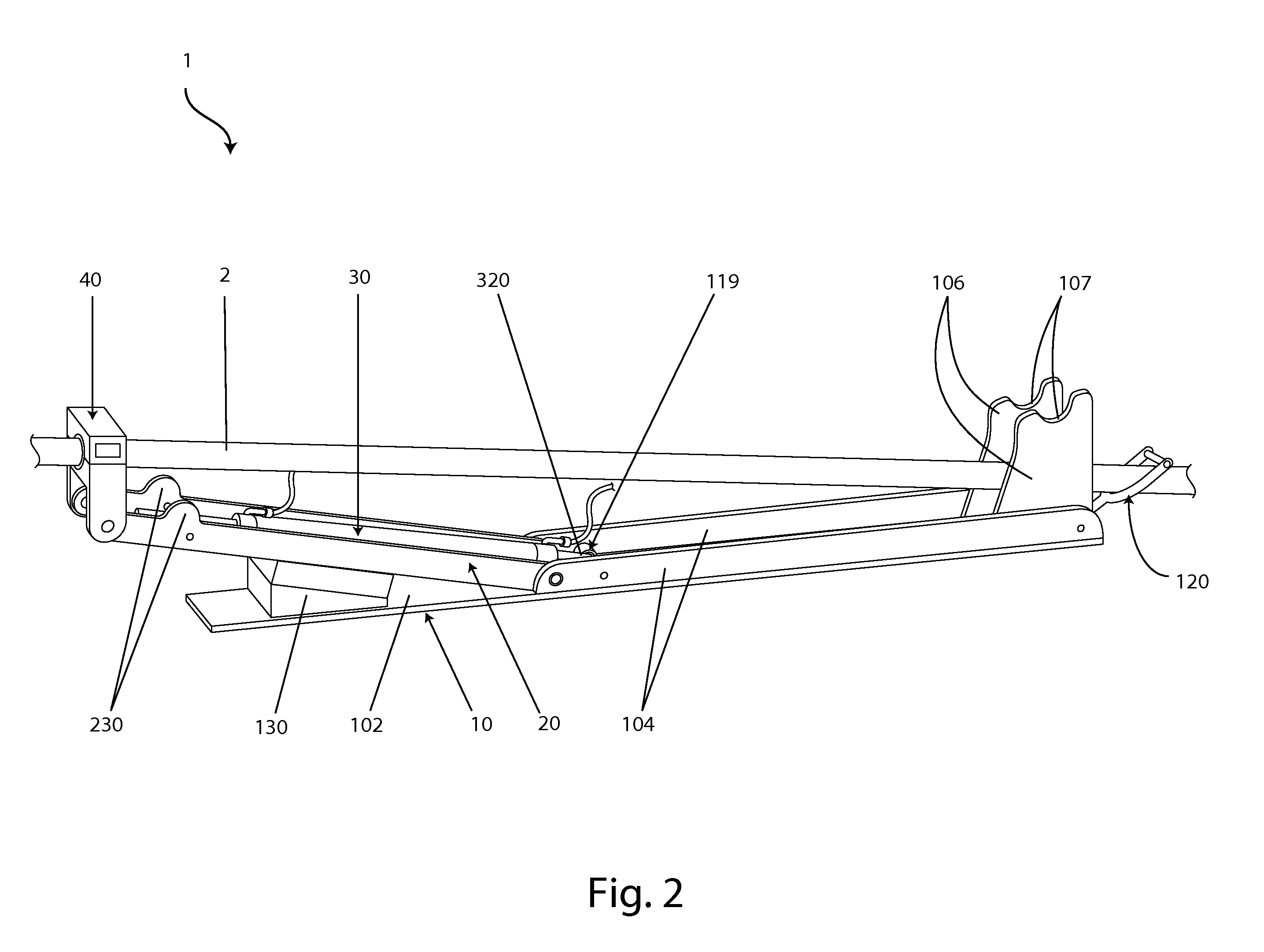
[0026]The trolling motor mount 1 is used to attach a trolling motor to a watercraft. The watercraft may be of any size, configuration, and use. A conventional trolling motor comprises a propulsion unit (a motor and propeller), shaft 2, and control housing. Referring collectively to FIGS. 1-6, the trolling motor mount 1 comprises a base 10, an arm assembly 20, an actuator 30, and a motor mounting assembly 40. The trolling motor mount 1 positions the trolling motor between an in-use, deployed position and an out-of-use, stowed position. In the deployed position, the motor's propulsion unit is submerged in the water and the shaft 2 is generally vertical (as in FIGS. 1 and 4), and in the stowed position, the propulsion unit is out of the water and the shaft 2 is generally horizontal (as in FIGS. 2 and 6).

[0027]The base 10 is fixedly attached to the watercraft's deck to secure the mount 1 to the watercraft. For example, the base 10 may comprises a plurality of holes for fastening the mou...


PUM


Abstract

A trolling motor mount comprising a base for attaching the mount to a watercraft, an arm assembly pivotally attached to the base, a motor mount assembly pivotally attached to the arm assembly for rotatably securing the trolling motor, and an actuator adapted to move the arm assembly between a fully deployed position and a fully stowed position. The actuator may comprise a linear actuator. The arm assembly may comprise a single elongated arm or a four bar linkage system. The mount may further comprise a user control such a switch, a wireless remote control, or wired remote control.

Description

CROSS-REFERENCE TO RELATED APPLICATIONS[0001]This application is a continuation-in-part of prior U.S. patent application Ser. No. 12 / 556,561, filed Sep. 9, 2009, which claims the benefit of U.S. Provisional Patent Application No. 61 / 109,985, filed Oct. 31, 2008, both of which are hereby incorporated by reference.BACKGROUND OF THE INVENTION[0002]1. Field of the Invention[0003]The present invention relates to trolling motors and, particularly, to a mount that attaches a trolling motor to a watercraft.[0004]2. Description of the Background[0005]A trolling motor slowly propels a watercraft, for example, yachts, fishing boats, motorboats, sailboat boats, and canoes, and allows for precise maneuvering. A trolling motor generally comprises an electric motor, propeller, shaft, and control housing. Trolling motors are often secondary to a larger primary gasoline or diesel motor and intended for use once the primary motor is shut down.[0006]Although pleasure and sport boaters use trolling mot...

Claims


Application Information

Patent Timeline
Patent Type & Authority Applications(United States)
IPC IPC(8): F16M5/00
CPCB63H20/007B63H20/10B63H21/30
Inventor TODD, WILLIAM J.WATSON, DOUGLAS D.
Owner TODD WILLIAM J
Why Eureka
Try Eureka