Projection optical system

a technology of projection optical system and projection optical plate, which is applied in the direction of printers, instruments, cameras, etc., can solve the problems of difficult to obtain a sufficiently large projection space such as in small and medium-sized meeting rooms or homes, and it is difficult for the conventional projector to project images onto a large screen. achieve the effect of reducing projection distance, increasing screen size, and high optical performan

Active Publication Date: 2010-05-13
KONICA MINOLTA OPTO
View PDF6 Cites 15 Cited by
  • Summary
  • Abstract
  • Description
  • Claims
  • Application Information

AI Technical Summary

Benefits of technology

[0044]According to the present invention, one or more reflective surfaces having an optical power are included and this makes it possible not only to increase the size of a screen but also to decrease a projection distance, and a focus mechanism is incorporated and this makes it possible to obtain a satisfactory projected image at an appropriate projection distance. Focus performed under predetermined conditions allows trapezoidal distortion produced when a projection distance is varied to be satisfactorily corrected. Thus, it is possible to provide a projection optical system that maintains high optical performance, has a significantly decreased projection distance and achieves focus according to a distance to a screen and a projection display apparatus incorporating such a projection optical system.

Problems solved by technology

However, the use of a conventional projector with a large screen makes it difficult to obtain a sufficiently large projection space such as in small- and medium-sized meeting rooms or homes.
In other words, unless a sufficiently large projection space is obtained, it is difficult for the conventional projector to project images onto a large screen.

Method used


Image

  • Projection optical system
  • Projection optical system
  • Projection optical system

Examples


examples

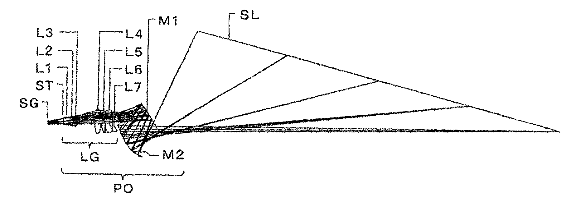
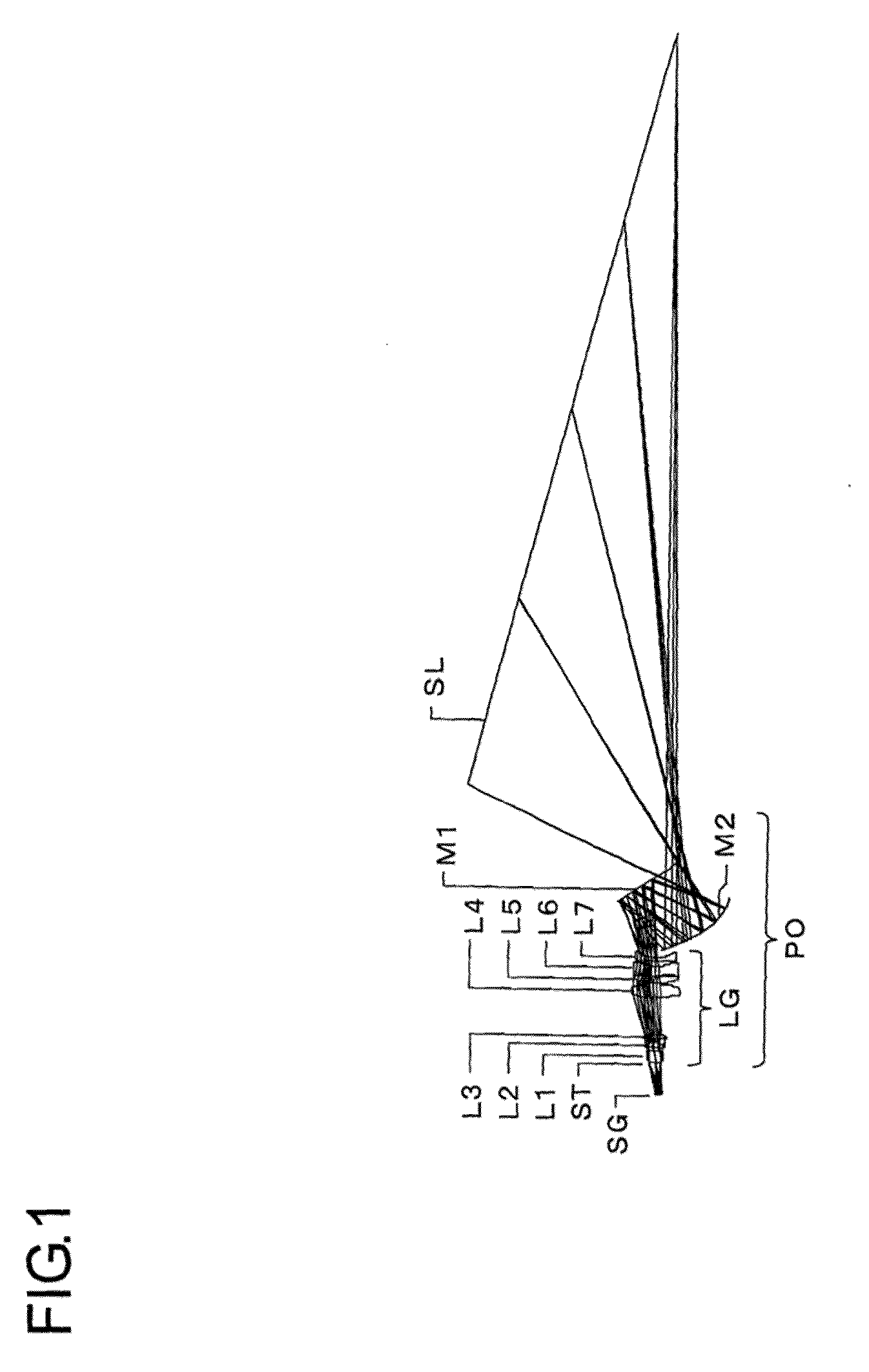
[0174]Projection optical systems and the like embodying the present invention will be more specifically described below with reference to construction data and the like. Examples 1 to 6 that will be described below are numerical examples corresponding to the first to sixth embodiments, respectively, described above. Ray diagrams (FIGS. 1, 4, 7, 10, 13 and 16) showing the optical constructions of the first to sixth embodiments show the corresponding optical arrangements, projection optical paths and the like of Examples 1 to 6, respectively.

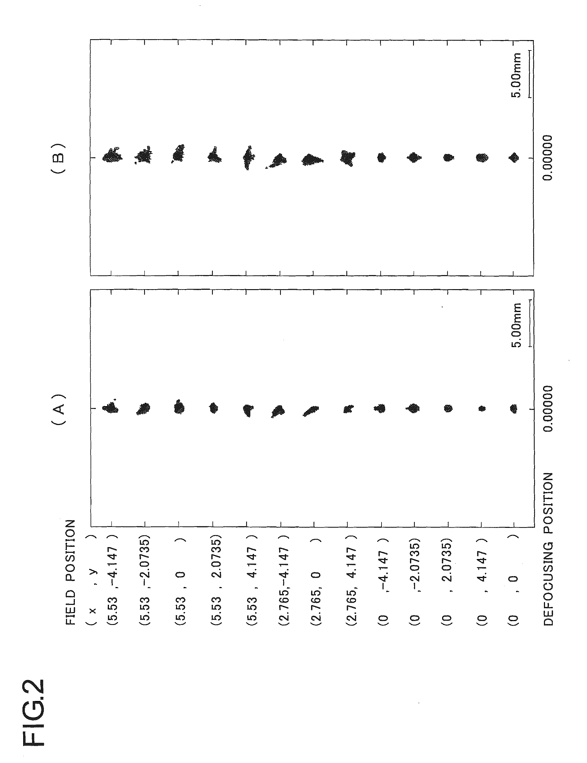
[0175]Tables 1 to 34 show the construction data of Examples 1 to 6; Table 35 shows projection magnifications (βx: the projection magnification in the direction of a long side of a screen, βy: the projection magnification in the direction of a short side of the screen) and the radius of the aperture R (mm) in the Examples; and Table 36 shows data and the like corresponding to the conditional formulas in the Examples. The data shown in Table 36 is b...


PUM


Abstract

A projection optical system satisfies the following conditional equation: 0.01<{(tan θ f1−tan θ f2)−(tan θ n1−tan θ n2)}·(β2/β1)<0.20. If, however, the normal line and longer side directions of a screen surface are z and x directions, respectively, an incident angle component on an xz-plane with respect to the screen surface is an incident angle θ, the larger incident angle θ of a light ray in light rays incident on respective edges of the upper and lower sides of the screen through the center of a stop is θ; f while the smaller incident angle θ of the light ray is θ n; θ f1 and θ f2: the maximum and minimum incident angles θ f at the maximum and minimum projecting magnification absolute values at a focus adjustment time, respectively, θ n1 and θ n2: the maximum and minimum incident angles θ n at the maximum and minimum projecting magnification absolute values at the focus adjustment time, respectively, and β1 and β2: the maximum and minimum incident magnifications at the maximum and minimum projecting magnification values at the focus adjustment time (if the magnification is negative, the magnification value is that at the absolute maximum or minimum time), respectively.

Description

TECHNICAL FIELD[0001]The present invention relates to a projection optical system and relates to, for example, a projection optical system that is incorporated in an image projection apparatus having a display device such as a liquid crystal display device or a digital micromirror device and that enlarges and projects an image on a display device surface onto a screen surface. The invention also relates to a projection optical instrument (in particular, a projection image display apparatus) incorporating such a projection optical system.BACKGROUND ART[0002]As highly portable computers (such as notebook personal computers) are becoming increasingly common, front projectors have come into widespread use in meetings and presentations in offices to enlarge and display images created on computers. As video information delivery such as digital broadcast is achieved in a variety of ways with higher resolution, projectors have come into widespread use even in homes where images are viewed o...

Claims


Application Information

Patent Timeline
Patent Type & Authority Applications(United States)
IPC IPC(8): G03B21/28
CPCG02B17/0816G03B21/28G03B21/00G03B21/005
Inventor YAMADA, KEIKOHAYASHI, KOHTAROOHZAWA, SOHIMAOKA, MASAYUKI
Owner KONICA MINOLTA OPTO
Why Eureka
Try Eureka