Microphone device and manufacturing method thereof

a microphone and manufacturing method technology, applied in the direction of piezoelectric/electrostrictive transducers, microphone structural associations, semiconductor electrostatic transducers, etc., can solve the problems of difficult to pick up sound faithfully, 12 khz frequency characteristics of microphones, and disadvantages, and achieve excellent stability and manufacturing. excellent stability, the effect of high accuracy

Inactive Publication Date: 2010-05-13
PANASONIC CORP
View PDF31 Cites 63 Cited by
  • Summary
  • Abstract
  • Description
  • Claims
  • Application Information

AI Technical Summary

Benefits of technology

[0057]According to the present invention, by disposing a cover comprising an acoustically-transmissive conductive structure over a MEMS microphone element with high accuracy and excellent stability manufactured using a MEMS technique, Helmholtz resonance at an audible frequency range can be avoided and flat frequency characteristics can be obtained and faithful sound pickup can be achieved easily even at a high region.
[0058]In other words, Helmholtz resonance at an audible frequency range can be avoided by a mesh structure formed in a cover.
[0059]Also, a one-modularized microphone device capable of performing stable sound pickup with high accuracy can be obtained by receiving a signal processor in addition to the microphone element inside the cover.
[0060]Also, a shielding effect of electromagnetic-wave noise can be obtained by forming a conductive mesh.
[0061]Also, a microphone device in which attachment to a mobile telephone etc. is facilitated, and positioning is facilitated in the case of mounting is implemented.

Problems solved by technology

In such a conventional MEMS microphone, it was found that frequency characteristics of the microphone have a disadvantage of having an output around a region of 12 kHz larger than one at 1 kHz by about 10 dB or more.
Essentially, the microphone desires flat frequency characteristics in order to pick up sound faithfully, but the microphone having such a peak of frequency characteristics has a problem of being difficult to pick up sound faithfully because a high region (region of a high frequency) is pronounced.

Method used


Image

  • Microphone device and manufacturing method thereof
  • Microphone device and manufacturing method thereof
  • Microphone device and manufacturing method thereof

Examples


first embodiment

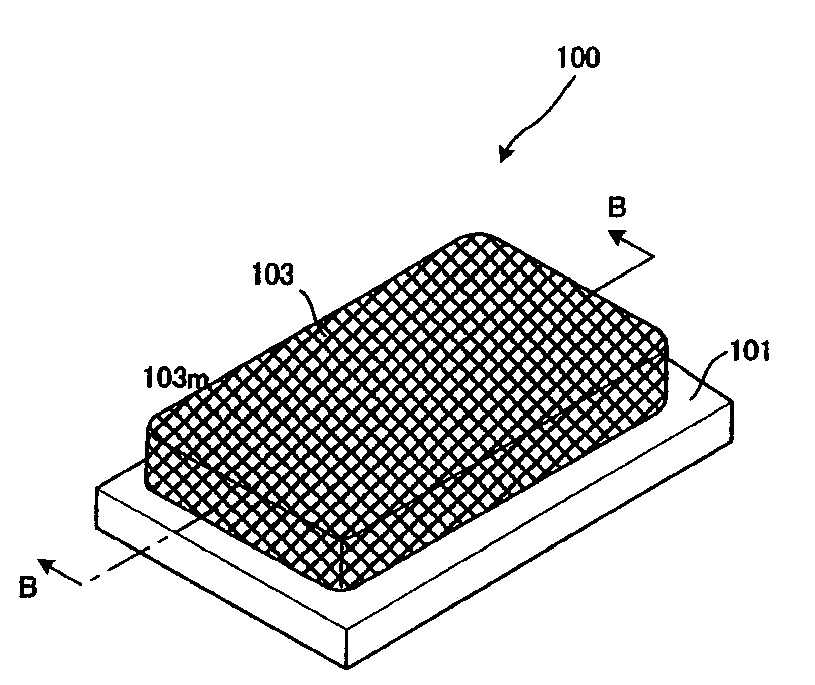
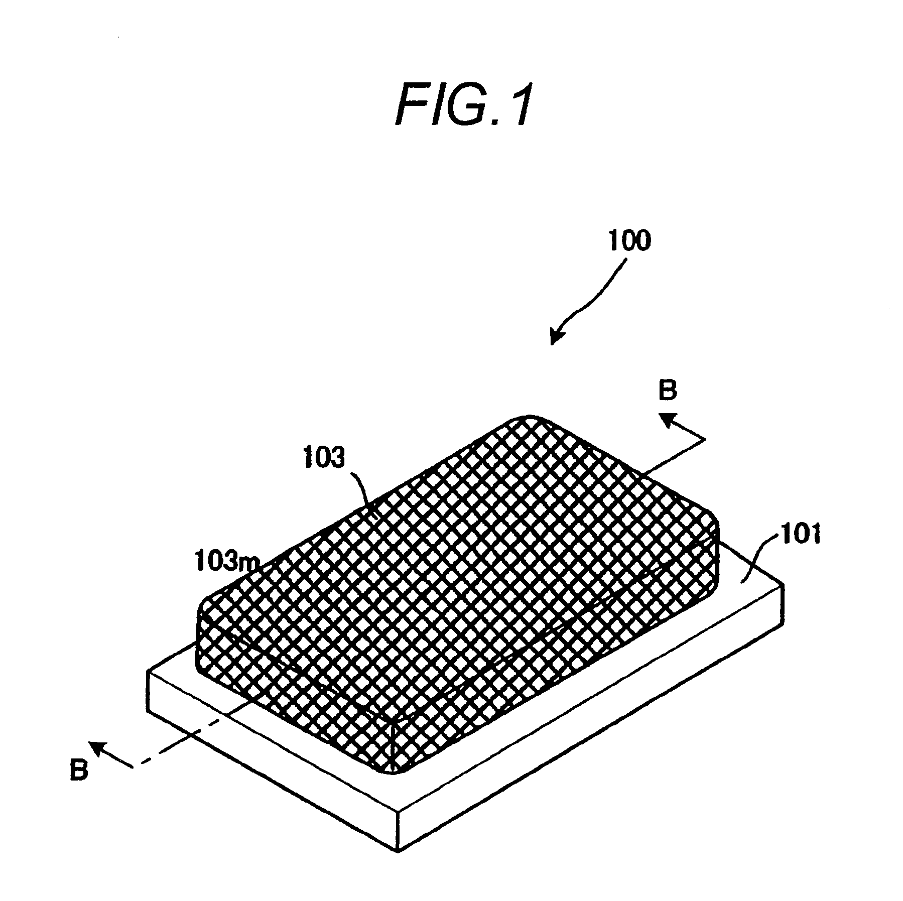
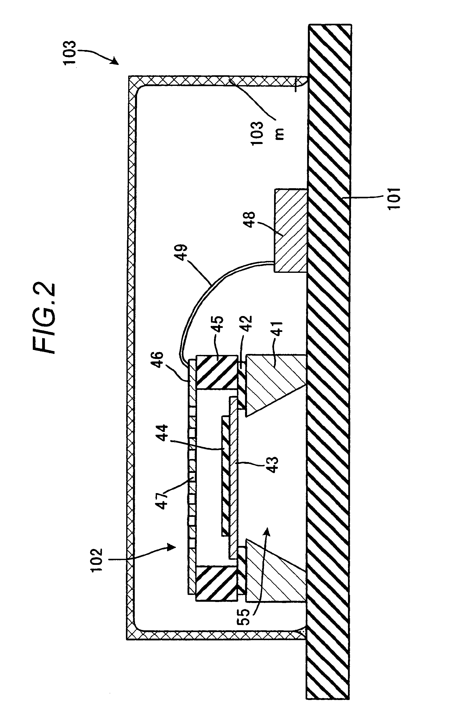
[0076]FIG. 1 shows an outline perspective view of an MEMS microphone 100 of the first embodiment. FIG. 2 shows a longitudinal sectional view (sectional view taken on line B-B of FIG. 1) of the MEMS microphone 100. As shown in FIGS. 1 and 2, the MEMS microphone 100 has a substrate 101, a MEMS chip 102 and a cover 103. FIGS. 1 and 2 are sectional views showing an example of the cover comprising an acoustically-transmissive mesh structure, and FIG. 2 is a sectional view showing a microphone element of a MEMS structure used herein.

[0077]This microphone device includes a microphone element manufactured using a semiconductor manufacturing process, a signal processor for performing predetermined arithmetic processing based on an output signal of the microphone element, and a cover 103 comprising an acoustically-transparent (acoustically-transmissive) mesh structure over the microphone element and the signal processor, and preventing Helmholtz resonance at an audible frequency range as show...

second embodiment

[0089]FIG. 3 is a sectional view showing another example of a microphone device of the present invention. In FIG. 3, the same numerals are assigned to portions common to the diagram described in the first embodiment.

[0090]The whole surface of the cover of the first embodiment shown in FIG. 2 is constructed by the mesh structure, but in the present embodiment, a mesh structure 103m is disposed corresponding to a MEMS chip 102 and the other region including a side surface is made of a metal substance as shown in FIG. 3.

[0091]The other portions than the cover are formed in a manner similar to the first embodiment. Here, the mesh structure 103m is disposed in an opening formed in the cover body 103s, and is bonded using an adhesive. The opening is formed in the cover so as to make sounds arrive at a vibrating plate of the microphone element.

[0092]For example, the mesh structure 103m is formed using a coarse mesh sheet (cloth). As the coarse mesh sheet, a knit-shaped mesh comprising stit...

third embodiment

[0095]FIG. 4 is a sectional view showing another example of a microphone device of the present invention. In FIG. 4, the same numerals are assigned to portions common to the diagrams described in the first and second embodiments.

[0096]The whole surface of the cover of the first embodiment shown in FIG. 2 is constructed by the mesh structure, but the embodiment is characterized in that a cover 103 has a punching metal (perforated structure) in which holes 103h are formed in a region opposed to a MEMS chip 102 as shown in FIG. 4.

[0097]The other portions than the cover are formed in a manner similar to the first embodiment.

[0098]The holes 103h are formed so as to become, for example, an aperture ratio of 25% or more.

[0099]Here, in the case of being constructed so that an audible frequency is set at 20 hHz and a parameter such as an aperture width d is obtained so as to become larger than this audible frequency and a resonance point becomes larger than its aperture width d, Helmholtz re...


PUM


Abstract

The present invention provides a microphone device with good frequency characteristics. The microphone device can pick up sound faithfully. In detail there is provided a microphone device comprising a microphone element, a signal processor, and a cover disposed over the microphone element and the signal processor, the cover including a mesh structure occupying 25% or more of at least one surface of the cover.

Description

BACKGROUND OF THE INVENTION[0001]1. Field of the Invention[0002]The present invention relates to a microphone device and a manufacturing method thereof, and particularly to a microphone device with excellent frequency characteristics.[0003]2. Description of the Background Art[0004]A cover is conventionally used in order to protect an electronic component such as a chip mounted on a substrate from powder dust or electromagnetic-wave noise, etc. from the outside.[0005]FIG. 10 shows an outline perspective view of a conventional MEMS microphone. FIG. 11A is a side view of the conventional MEMS microphone.[0006]FIG. 11B is a plan view of the conventional MEMS microphone. FIG. 11C is a cross-sectional view taken along line A-A in FIG. 10, showing the conventional MEMS microphone.[0007]The conventional MEMS microphone 300 shown in FIGS. 10 and 11A to 11C includes a substrate 301, a MEMS chip 200 and a cover 303. Here, the MEMS chip 200 is a chip constructing a microphone element for conver...

Claims


Application Information

Patent Timeline
Patent Type & Authority Applications(United States)
IPC IPC(8): H04R9/08
CPCH04R1/04H04R2499/11H04R19/005H01L2224/48091H01L2924/16152H01L2924/00014
Inventor OHTSUKA, YOSHIO
Owner PANASONIC CORP
Why Eureka
Try Eureka