
Composite fastener for ceramic components

a technology of ceramic components and fasteners, which is applied in the direction of threaded fasteners, couplings, rod connections, etc., can solve the problems of relative brittleness of ceramic components, rapid cracking of ceramic components, and soon after catastrophic failure modes, so as to increase mechanical strength

Inactive Publication Date: 2010-05-13
SGL CARBON SE
View PDF40 Cites 10 Cited by
  • Summary
  • Abstract
  • Description
  • Claims
  • Application Information

AI Technical Summary

Benefits of technology

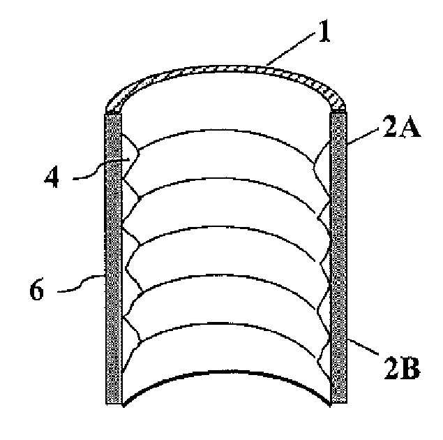
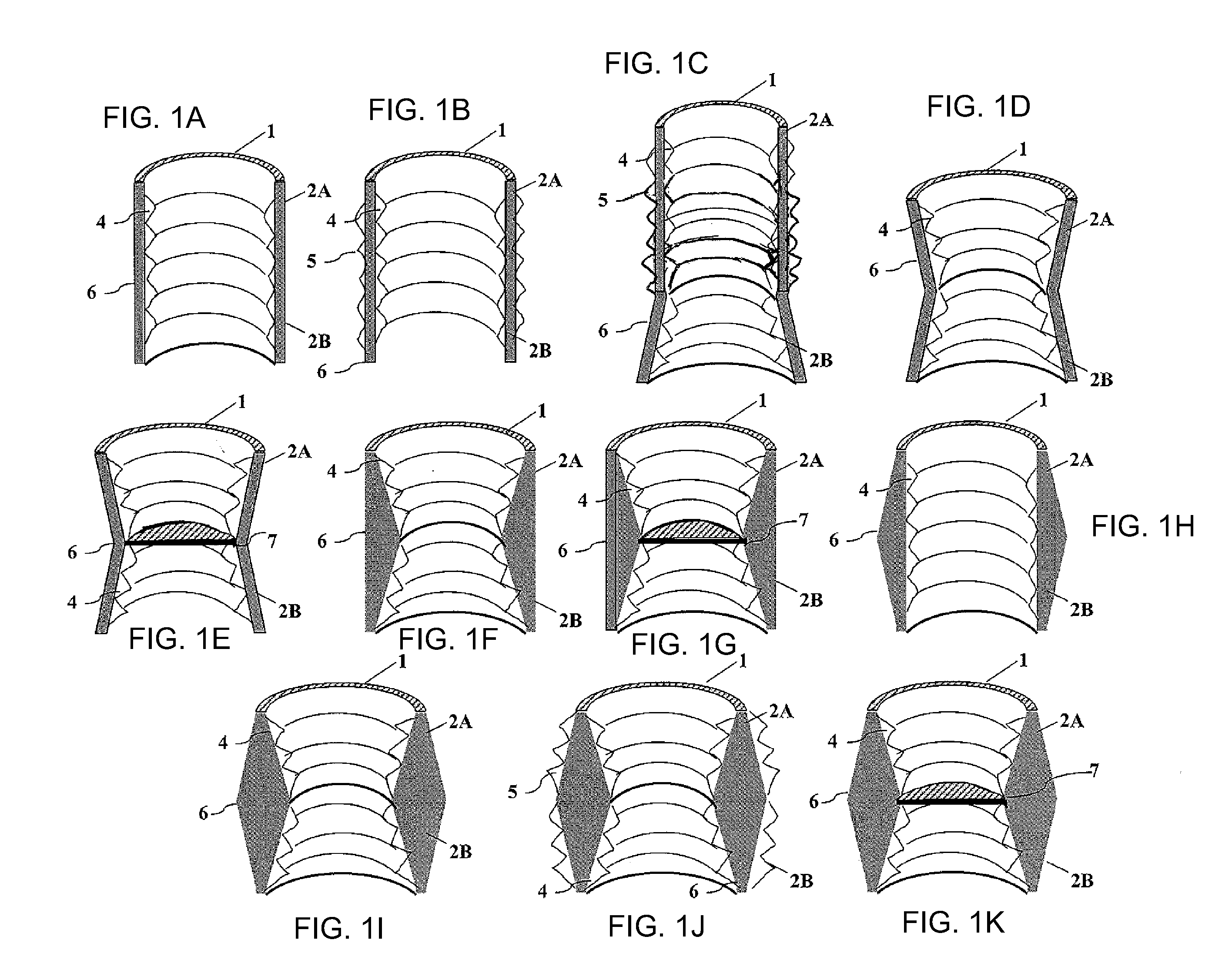
[0015]The tubular member is preferably shaped symmetrical with respect to its rotational axis, but may also be formed slightly ellipsoidal. The latter shape provides a measure to prevent unscrewing.
[0018]According to one embodiment, both the internal surface as well as the external surface of the said tubular member are axially tapered towards their rotational axis thus forming an inverted bi-conical tube. The taper angle of internal and external surfaces are not necessarily alike. The taper angle of the external surface may be smaller than that of the internal surface to increase the mechanical strength at the equator region where both inverted cones meet.

Problems solved by technology

While a screw may be a perfect connecting mean if made of metal or wood, it will always be a compromise when it is made of inorganic fibers, as latter are known to be rather brittle but typically show a good if not exceptional strength under tension.
Besides said drawbacks of the conventional screw design, if it is used to connect ceramic members that are subject to mechanical load and / or temperature changes, the relatively brittle ceramic member quickly starts to crack and very may soon after experience catastrophic failure modes.

Method used


Image

  • Composite fastener for ceramic components
  • Composite fastener for ceramic components
  • Composite fastener for ceramic components

Examples


example

[0110]A roving consisting of 5 bundles of 12000 high-modulus PAN-based carbon fibers (diameter: 10 μm) was impregnated, under tension, with a phenolic resin at a volume ratio of 50 (carbon fiber): 50 (phenolic resin), to produce a carbon fiber-containing resin film of 200 μm in thickness in which the carbon fibers were arranged in the same direction.

[0111]An aluminum-made cylindrical mandrel was provided with threaded grooves.

[0112]This carbon fiber-containing resin film was wound around the mandrel in a plurality of layers so that the carbon fiber in each layer was arranged so that 50% by weight of the fibers were arranged in a direction with an angle of ±(10 to 20)° to the cylinder axial direction and 50% by weight of the fibers forming said tubular member are arranged in a direction making an angle of ±(70 to 90)° to the cylinder axial direction relative to the cylinder axial direction. Thereafter, a shrink tape was wound thereon. The resulting laminate was heated for curing.

[011...


PUM

PropertyMeasurementUnit
lengthaaaaaaaaaa
angleaaaaaaaaaa
angleaaaaaaaaaa

Abstract

A tubular composite member with two ends for connecting ceramic components made of a composite of an inorganic matrix reinforced with inorganic fibers is formed with an at least partially threaded internal surface and an external surface. A ceramic member has at least one surface formed with one or more annular grooves with an inner shell surface, an outer shell surface, and a root. The inner shell surface is at least partially threaded. A resulting ceramic member assembly includes at least two ceramic members connected by at least one tubular composite member. The ends of the tubular composite member are screwed into the corresponding annular groove of two adjacent ceramic members. The such fastened / joined ceramic members can be operated at high temperatures especially under thermal cycling and / or thermal shock conditions as well as dynamic mechanical load in different directions. Methods to manufacture tubular composite members according to this invention are described.

Description

CROSS-REFERENCE TO RELATED APPLICATION[0001]This application is a continuation, under 35 U.S.C. §120, of copending international application No. PCT / EP2008 / 056614, filed May 29, 2008, which designated the United States; this application also claims the priority, under 35 U.S.C. §119, of European patent application No. EP 07 109 159.9, filed May 29, 2007; the prior applications are herewith incorporated by reference in their entirety.BACKGROUND OF THE INVENTION[0002]Field of the Invention[0003]The present invention relates to a fastening or connecting element for technical ceramic components.[0004]Technical ceramics and especially fiber-reinforced ceramics belong to the group of increasingly important materials for various industrial as well as space applications due to their high temperature resistance combined with a low specific weight and other more unique properties.[0005]Technical (also referred to as advanced, engineering, new or fine) ceramics according to this invention are ...

Claims


Application Information

Patent Timeline
Patent Type & Authority Applications(United States)
IPC IPC(8): F16D1/02F16B37/00B29C53/76
CPCF16B5/0088Y10T403/44F16B33/006E04F13/08E04F13/14F16B33/00
Inventor MONTMINY, JOHNHINGST, KARLKRAUS, THOMASKLOTZ, CHRISTIAN
Owner SGL CARBON SE
Learn More