Self-drilling screw with multi-drilling portions

a screw and self-drilling technology, applied in the direction of screws, threaded fasteners, fastening means, etc., can solve the problems of screw snapping, screw entanglement, screwing torque increase, etc., to reduce screwing torque, increase screwing efficiency, and speed up drilling

Inactive Publication Date: 2010-05-13
CHAN LIANG ENTERPRISE
View PDF13 Cites 10 Cited by
  • Summary
  • Abstract
  • Description
  • Claims
  • Application Information

AI Technical Summary

Benefits of technology

[0008]The object of the present invention is to provide a self-drilling screw with multi-drilling portions to achieve a speedy drilling and a decreased screwing torque so as to increase the screwing efficiency.
[0009]The self-drilling screw in accordance with the present invention mainly comprises a head, a shank outwardly extended from the head forming a drilling portion to be disposed opposite to the head, and a set of thread section spiraling round the shank. Wherein, at least one sub-drilling portion is further defined between the drilling portion and the thread section and comprised of a sequence of indentations for rendering the performance of a plurality of cutting ridges. In this manner, the sub-drilling portion along with the cutting ridges assists the drilling portion in advancing a preferable preliminary drilling and has the indentations to provide an efficient extrusion of debris, therefore conducing to attaining a decreased screwing resistance and torque, achieving a rapid screwing, and promoting the screwing efficiency.

Problems solved by technology

However, in virtue of the typical punching upon the drilling portion 13 and the sole application of the flutes 131 and cutting edges 133 for processing the cutting and debris guidance, a limited accommodation of debris among the flutes 131 becomes easy to impede the extrusion of the debris in time of drilling and to incur an increment of the screwing torque, which relatively results in snapping of the screw 1.
Therefore, once the drilling portion 13 is prolonged, the larger and lengthy die is required, which potentially results in the exhaustion of the die under a term of utilization and renders the high manufacturing cost.
However, the thinner and fragile necking 25 with the reduced diameter d1 would be subjected to a facile snap in view of its lower resistance unable to bear the drilling pressure, which however would decrease the screwing capability and firmness of the screw 2.

Method used


Image

  • Self-drilling screw with multi-drilling portions
  • Self-drilling screw with multi-drilling portions
  • Self-drilling screw with multi-drilling portions

Examples


Embodiment Construction

[0019]Before describing in greater detail, it should note that the like elements are denoted by the similar reference numerals throughout the disclosure.

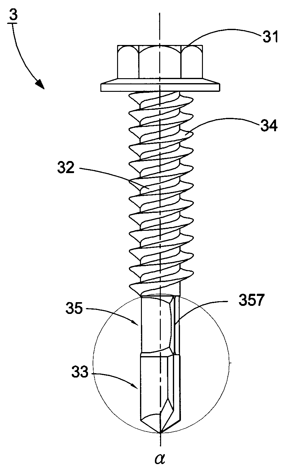
[0020]Referring to FIG. 3 showing the present invention, a self-drilling screw 3 of a first preferred embodiment comprises a head 31, a shank 32 outwardly extended from the head 31 forming a drilling portion 33 to be disposed opposite to the head 31, and a set of thread section 34 spiraling round the shank. Wherein, the drilling portion 33 includes a drill bit 331 defined thereon and at least one flute 332 disposed on the drill bit 331. Particularly, a sub-drilling portion 35 is defined between the drilling portion 33 and the thread section 34. It should be noted that the sub-drilling portion could be directly and integrally punched by a mold, which further results in a higher strength.

[0021]Moreover, the sub-drilling portion 35 further includes a sub-drill body 351, an upper region 352 disposed close to the edge of the thread secti...


PUM


Abstract

A self-drilling screw with multi-drilling portions mainly comprises a shank, a head and a drilling portion separately disposed on both ends of the shank, and a thread section spiraled on the shank. Wherein, at least one sub-drilling portion formed amid the drilling portion and the thread section further defines a sequence of indentations and prominent areas, and each indentation generates a cutting surface outwardly extended from one side thereof so as to converge the cutting surface with the adjacent prominent area at a cutting ridge. Accordingly, the application of the cutting ridges and the indentations facilitates the drilling portion with the chipping capability and renders an appropriate guidance to redundant debris, thereby efficiently achieving a swift screwing and the lowered screwing resistance to promote the screwing efficiency.

Description

BACKGROUND OF THE INVENTION[0001]1. Field of the Invention[0002]The present invention relates to a self-drilling screw, in particular to a self-drilling screw including multi-drilling portions.[0003]2. Description of the Related Art[0004]A conventional drilling screw 1 as shown in FIG. 1 comprises a head 11, a shank 12 outwardly extended from the head 11 forming a drilling portion 13 at the distal end thereof, and a set of thread section 14 spiraling round the shank 12. Wherein, the drilling portion 13 peripherally defines two flutes 131 (only one flute as viewed in the FIG. 1), and a cutting surface 132 is further outwardly extended from the flute 131 so that a cutting edge 133 is formed by the convergence of the flute 131 and the adjoining cutting surface 132. During operation, the cutting edge 132 renders a preliminary drilling to lead the succeeding thread section 14 screwing into an object (not shown) and fix the screw 1 therein.[0005]However, in virtue of the typical punching ...

Claims


Application Information

Patent Timeline
Patent Type & Authority Applications(United States)
IPC IPC(8): F16B25/10
CPCF16B25/103F16B25/0084
Inventor LIN, KUO-CHANG
Owner CHAN LIANG ENTERPRISE
Why Eureka
Try Eureka