Tool with Remote Switch

Inactive Publication Date: 2008-09-11
KREG ENTERPRISES
View PDF63 Cites 9 Cited by
  • Summary
  • Abstract
  • Description
  • Claims
  • Application Information

AI Technical Summary

Benefits of technology

[0013]In one embodiment, the handle is a lever and the user operates the device by first positioning the material to be drilled and then pulling the lever forward. This motion activates the switch, which in turn activates the drill motor and further throws or moves the clamp assembly. The drill stroke is completed by continuing to pull on the lever and then returning the lever to its home position. Although the

Problems solved by technology

Such a process is inconvenient and time-consuming.
Additionally, such clamps do not readily accommodate common material thicknesses.
Other devices utilize a one-step process, but requ

Method used


Image

  • Tool with Remote Switch
  • Tool with Remote Switch
  • Tool with Remote Switch

Examples


Example

[0022]In the following detailed description of embodiments of the invention, reference is made to the accompanying drawings that form a part hereof, and in which is shown by way of illustration specific preferred embodiments in which the subject matter may be practiced. These embodiments are described in sufficient detail to enable those skilled in the art to practice them, and it is to be understood that other embodiments may be utilized and that mechanical, structural, electrical, and procedural changes may be made without departing from the spirit and scope of the present subject matter. The following detailed description is, therefore, not to be taken in a limiting sense, and the scope of embodiments of the present invention is defined only by the appended claims and their equivalents.

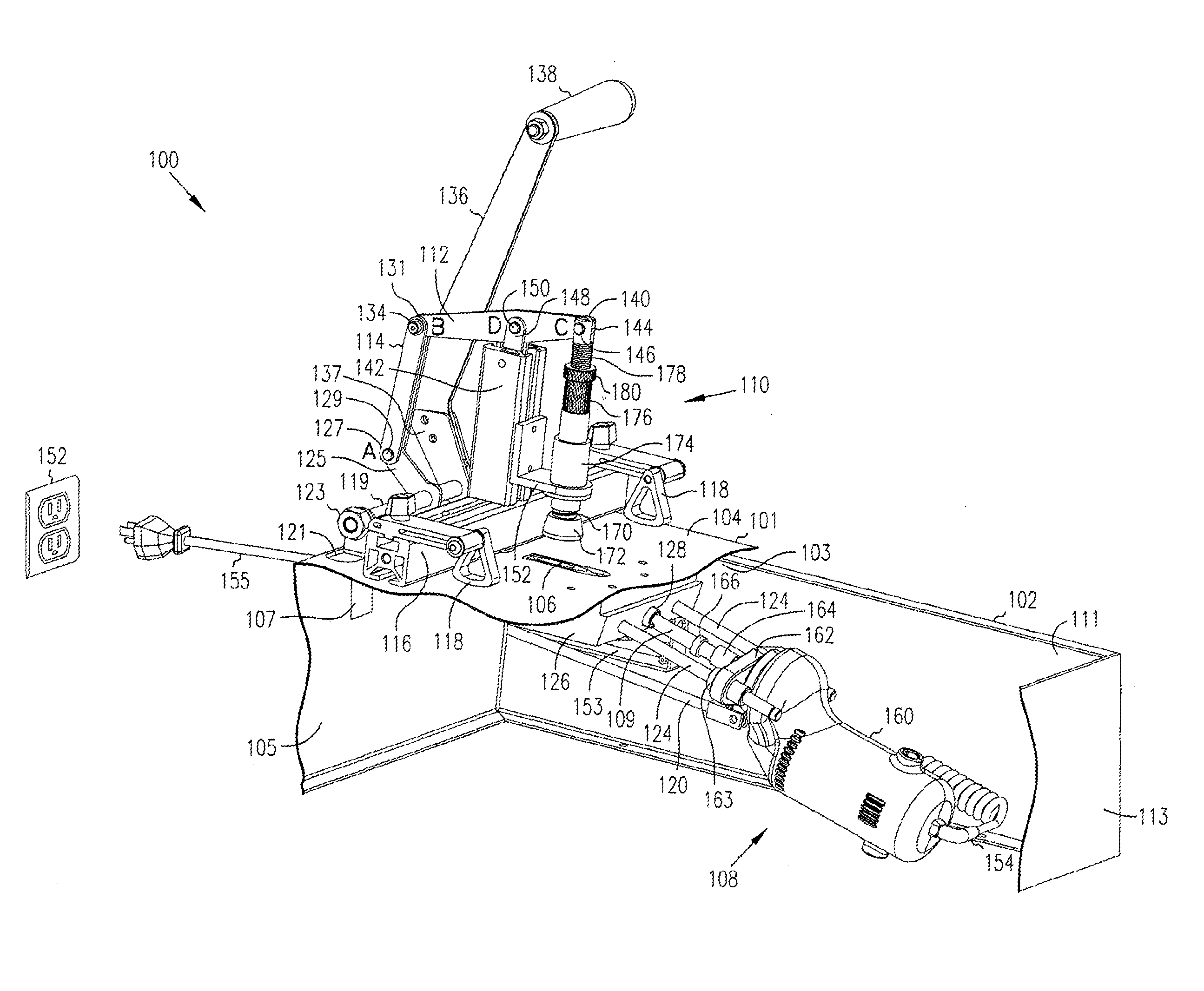
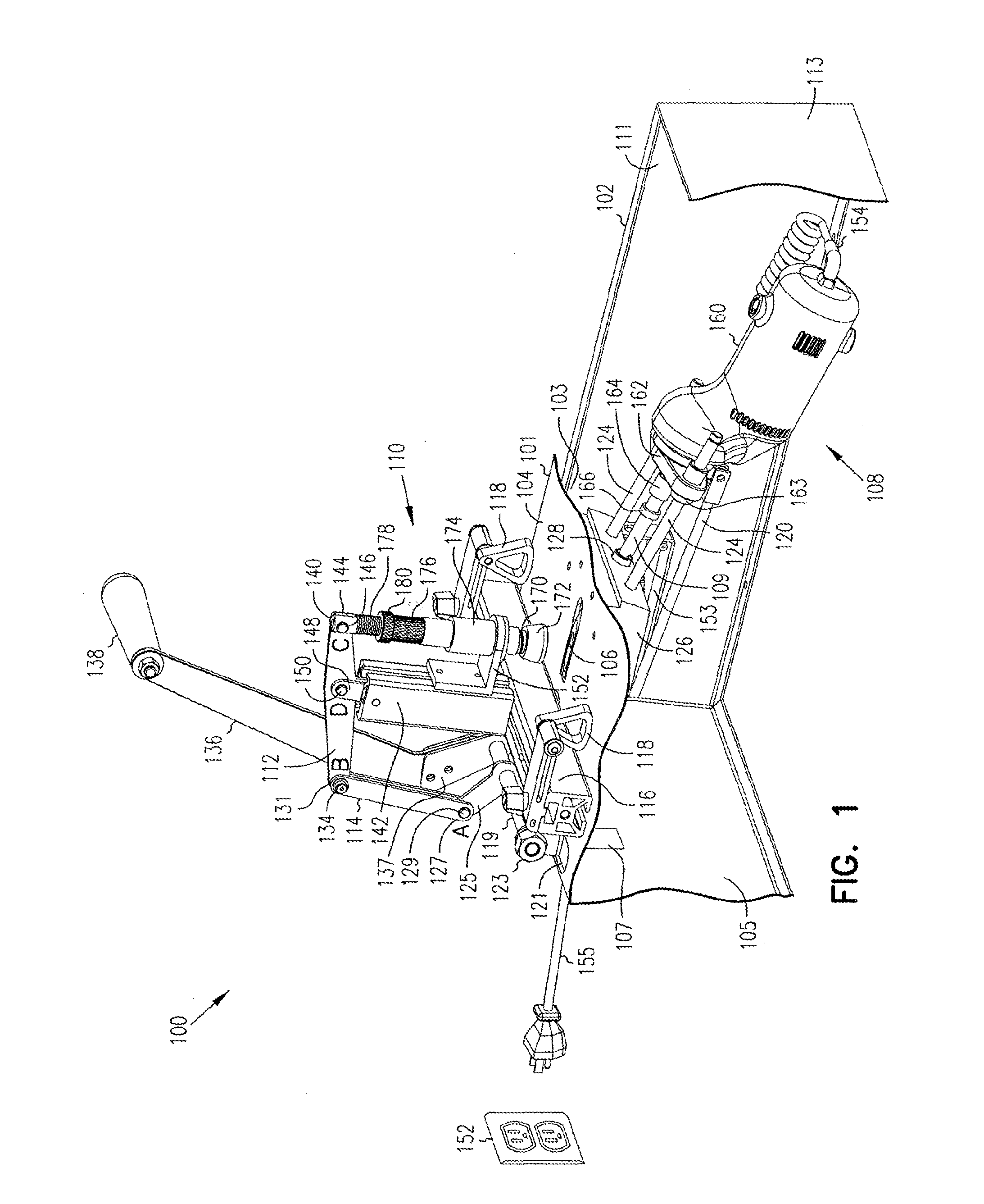
[0023]FIG. 1 shows one embodiment of a novel pocket hole boring machine 100. In this embodiment, the machine 100 comprises a cabinet 102 housing a drill 108 pivotally connected to an adjustable cla...


PUM


Abstract

A non-pneumatic system for use with a workpiece is described. A clamp assembly having a clamp pad is secured to the cabinet. An electrically operated tool is movably secured to the cabinet. The tool has a remote switch which when activated in turn activates the tool. A lever (e.g., a handle) is operatively coupled to the clamp assembly and the tool. When the lever is manually moved, the remote switch is activated and the clamp pad moves towards the work surface. Preferably, the tool also moves towards the work surface opening by manually moving the lever. For example, the tool utilized in this non-pneumatic system may be a drill or saw.

Description

CROSS-REFERENCE TO RELATED APPLICATION[0001]This application is a divisional of application Ser. No. 11 / 210,588, filed 24 Aug. 2005, entitled “Non-Pneumatic Clamp and Drilling System,” and issued as U.S. Pat. No. ______ on ______, 2008, which claims the benefit under 35 U.S.C. 119 (e) of U.S. Provisional Application No. 60 / 603,976 filed on 24 Aug. 2004, entitled “Pocket Hole Boring Machine,” both of which are incorporated herein by reference.FIELD OF THE INVENTION[0002]The present subject matter relates generally to drilling, and, more particularly, to a one-step drilling system and methods of using same.BACKGROUND OF THE INVENTION[0003]There are many types of machines in use today for drilling holes such as dowel holes, pocket holes, and so forth, in various types of workpieces. Pocket hole wood joinery involves joining boards by inserting a fastener at an angle through the edge of one board into the other. Such joints are commonly used for face frames, cabinet boxes, leg-to-rail j...

Claims


Application Information

Patent Timeline
IPC IPC(8): B23B29/02
CPCB23B47/287B23B2247/10B23B2247/12B23D47/04B25B5/12Y10T408/165Y10T408/563Y10T408/83Y10T408/885Y10T408/5626B27C3/02
Inventor SOMMERFELD, CRAIG A.CLARK, SCOTT L.
Owner KREG ENTERPRISES
Why Eureka
Try Eureka