Heatable part of a pump housing

a pump housing and heat sink technology, applied in the direction of machines/engines, liquid fuel engines, positive displacement liquid engines, etc., can solve the problem of unproblematic movement, and achieve the effect of extending the contact area

Inactive Publication Date: 2010-05-13
EICHENAUER HEIZELEMENTE
View PDF7 Cites 21 Cited by
  • Summary
  • Abstract
  • Description
  • Claims
  • Application Information

AI Technical Summary

Benefits of technology

[0010]To establish a large-surface contact between the tubular heating element and the heat distribution sheet in a reliable manner, the tubular heating element of a housing part according to this invention preferably has a more or less angular cross-section. For example, the tubular heating element can have an approximately rectangular, trapezoidal or triangular cross-section. In that case, it is preferred if the lower side of the tubular heating element, i.e. the side facing the pump housing, encases an angle less than 90°, particularly 60° to 80°, with an adjacent side. Thus, an enlarged contact area can be created easily and reliably between the tubular heating element and the heat distribution sheet. As another option, a rounded tubular heating element can be fixed in an groove having a round bottom, e.g. in a groove with a semi-circular cross-section.
[0011]Preferably, the heat distribution sheet extends on both the sides of the groove or step, so that the heat generated by the tubular heating element is spread quickly over a maximum possible area of the housing part.
[0012]Preferably, the tubular heating element is arranged in a groove of the housing part that is covered by the heat distribution sheet. This offers the advantage that an even larger area of contact can be created between the tubular heating element and the heat distribution sheet, as compared to the arrangement of the tubular heating element in a step, because a groove with a trapezoidal or rectangular cross-section is formed by two steps; and this enables the heat distribution sheet to touch the tubular heating element on three side faces.

Problems solved by technology

It is generally known that the process of soldering a tubular heating element to a heat distribution sheet and the heat distribution sheet to a steel body causes relative movements between the tubular heating element and the heat distribution sheet as well as between the heat distribution sheet and the steel body due to the heating in a soldering furnace; these movements are unproblematic only in case of soldered joints on plane surfaces.

Method used


Image

  • Heatable part of a pump housing
  • Heatable part of a pump housing

Examples


Embodiment Construction

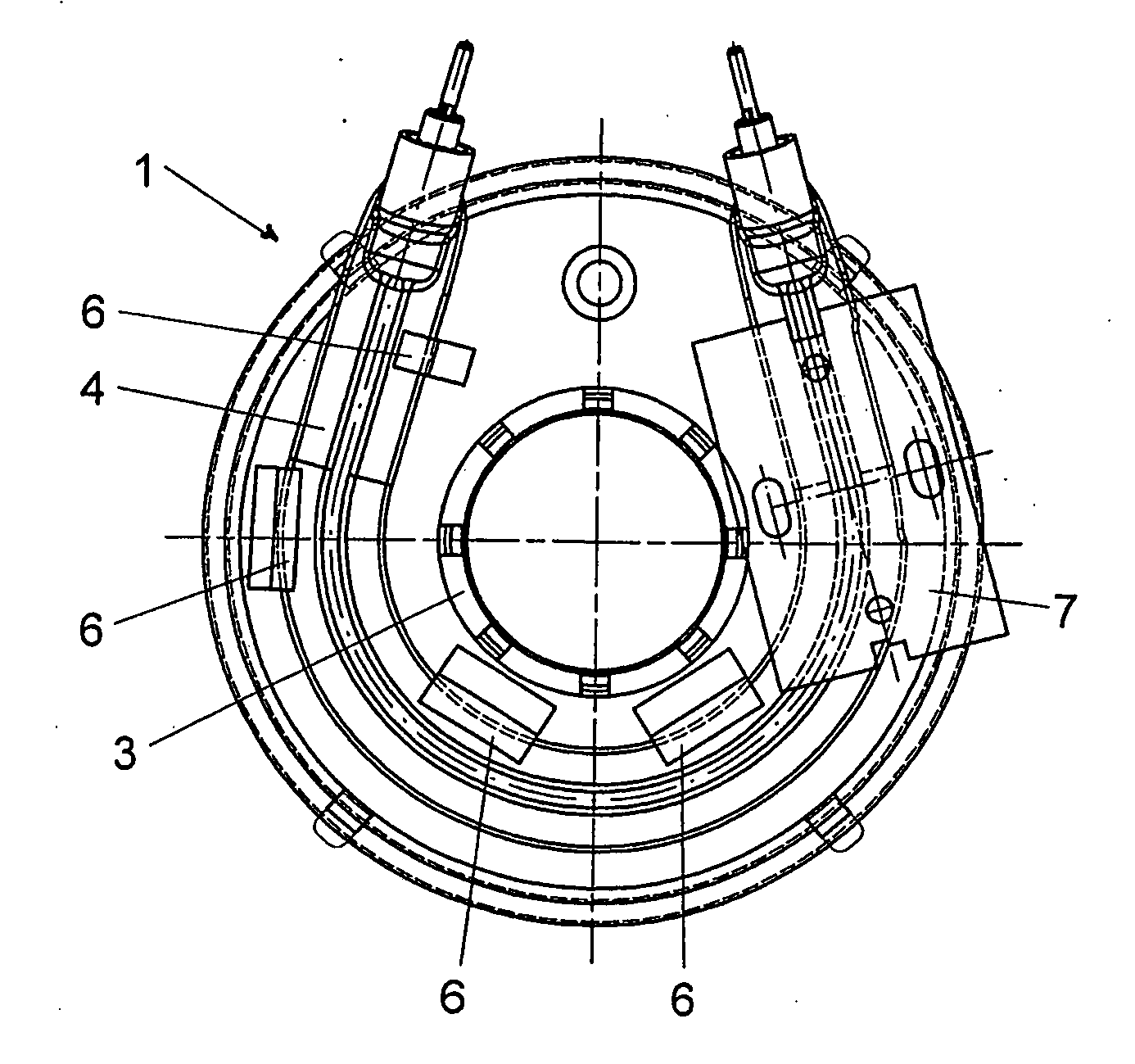
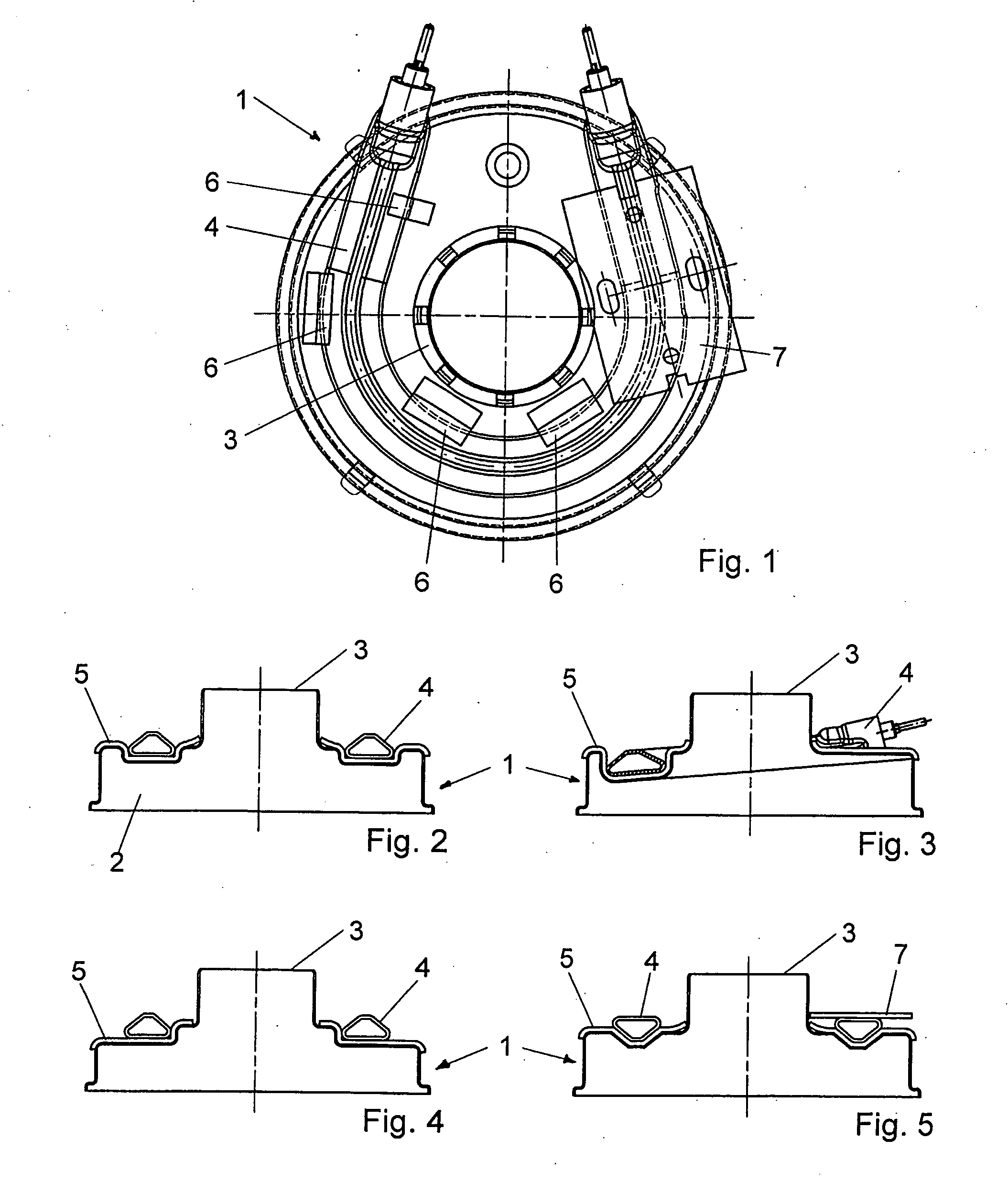
[0019]The pump housing part 1 shown in FIGS. 1 and 2 is a cap. The housing part 1 has a base body made of stainless steel 2 forming a connecting tube 3. The pump housing part 1 can be heated with a U- or C-shaped tubular heating element 4, which is soldered onto a heat distribution sheet 5 that spreads over a cover surface of the housing part and is soldered with it.

[0020]As shown in the sectional view of FIG. 2, the heat distribution sheet 5 covers a U- or C-shaped groove in the housing part. The groove can have an angular cross-section, particularly rectangular or trapezoidal, or a U-shaped cross-section. The tubular heating element 4 is arranged in this groove, such that it touches both the side walls of the groove. On both the sides, the heat distribution sheet 5 projects by more than 0.5 cm beyond the side walls of the groove. An advantage of this is that a larger area of contact is created between the tubular heating element 4 and the heat distribution sheet 5. It is preferred...


PUM


Abstract

The description relates to a heatable pump housing part comprising a heat distribution sheet fixed on the housing part and a tubular heating element fixed on the heat distribution sheet. According to the invention the tubular heating element is positioned in a groove or a step on the housing part that is covered by the heat distribution sheet.

Description

[0001]This invention refers to a heatable part of a pump housing on which a heat distribution sheet is fixed on which a tubular heating element is arranged. Such a pump housing part is known from DE 199 03 951 A1. Heatable pump housing parts are, for example, required for washing machines or dishwashers.[0002]The pump housing known from DE 199 03 951 A1 has an aluminium heat distribution sheet fixed on a flat or conical cover surface. The heat distribution sheet distributes the heat generated from a tubular heating element, which is soldered onto the plate, quickly over a large area and transmits it to the stainless steel housing part situated below it.[0003]Furthermore, EP 1 507 914 B1 discloses another pump housing part. A tubular heating element is arranged in a suitably shaped groove of the housing part. To facilitate a good heat coupling between the tubular heating element and the housing part, joints and any free spaces between the tubular heating element and the walls and bot...

Claims


Application Information

Patent Timeline
Patent Type & Authority Applications(United States)
IPC IPC(8): F04C29/04A47L15/42
CPCF04D29/588F04D29/426
Inventor BREDL, DANIELSCHLACHTER, ULRICHSPIEGEL, CHRISTIANLANG, ARMIN
Owner EICHENAUER HEIZELEMENTE
Why Eureka
Try Eureka