Ventilation flap arrangement

Inactive Publication Date: 2010-05-13
EUWE EUGEN WEXLER HLDG GMBH & CO KG
View PDF7 Cites 10 Cited by
  • Summary
  • Abstract
  • Description
  • Claims
  • Application Information

AI Technical Summary

Benefits of technology

[0005]The invention is based on the object of providing a ventilation flap arrangement and a method for producing a ventilation flap arrangement of this type with regard to an econom

Problems solved by technology

These production methods require expensive tools and optionally injection moulding machines adapted thereto.
The production of a ventilation flap arrangement by the multi-compone

Method used


Image

  • Ventilation flap arrangement
  • Ventilation flap arrangement
  • Ventilation flap arrangement

Examples


Example

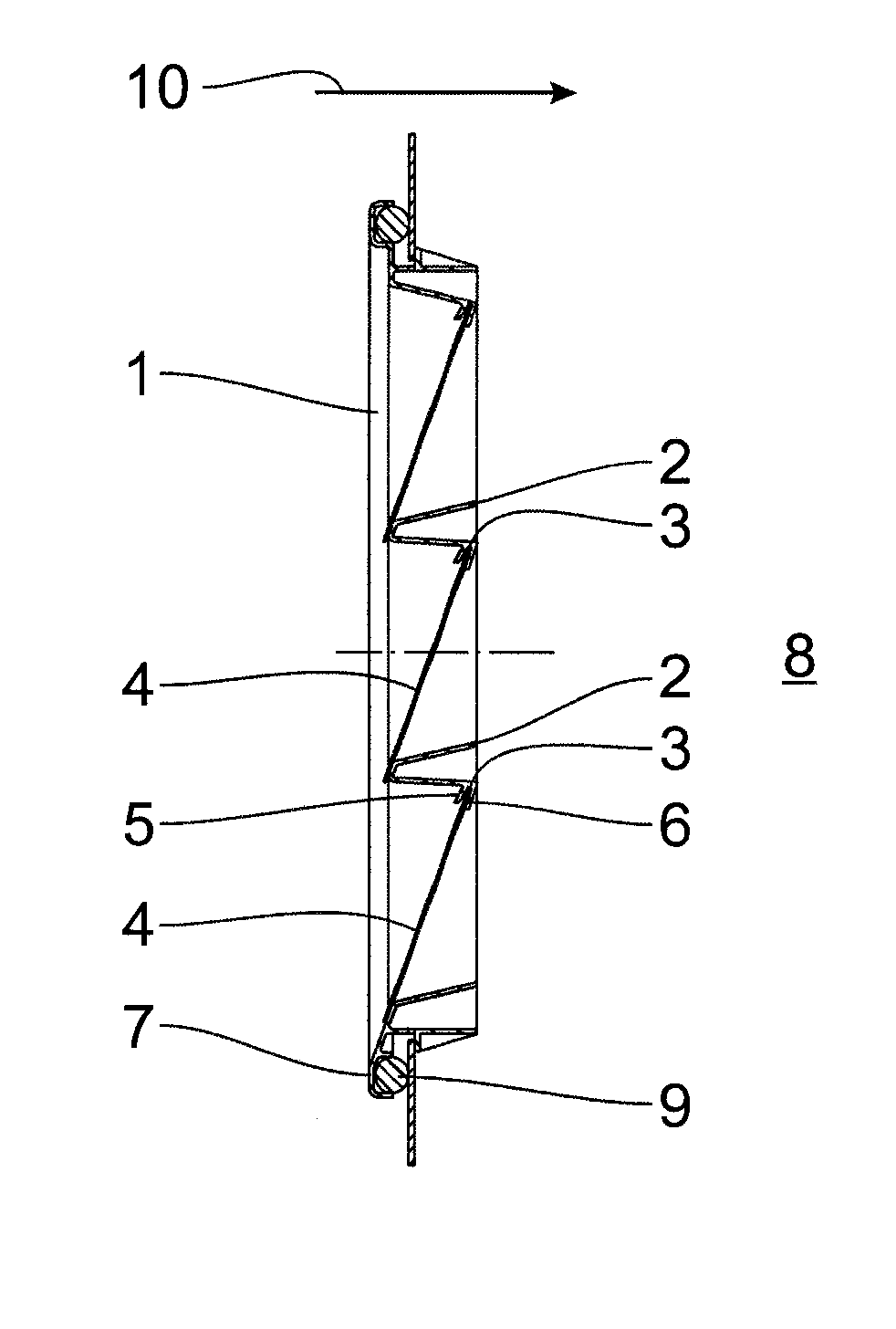
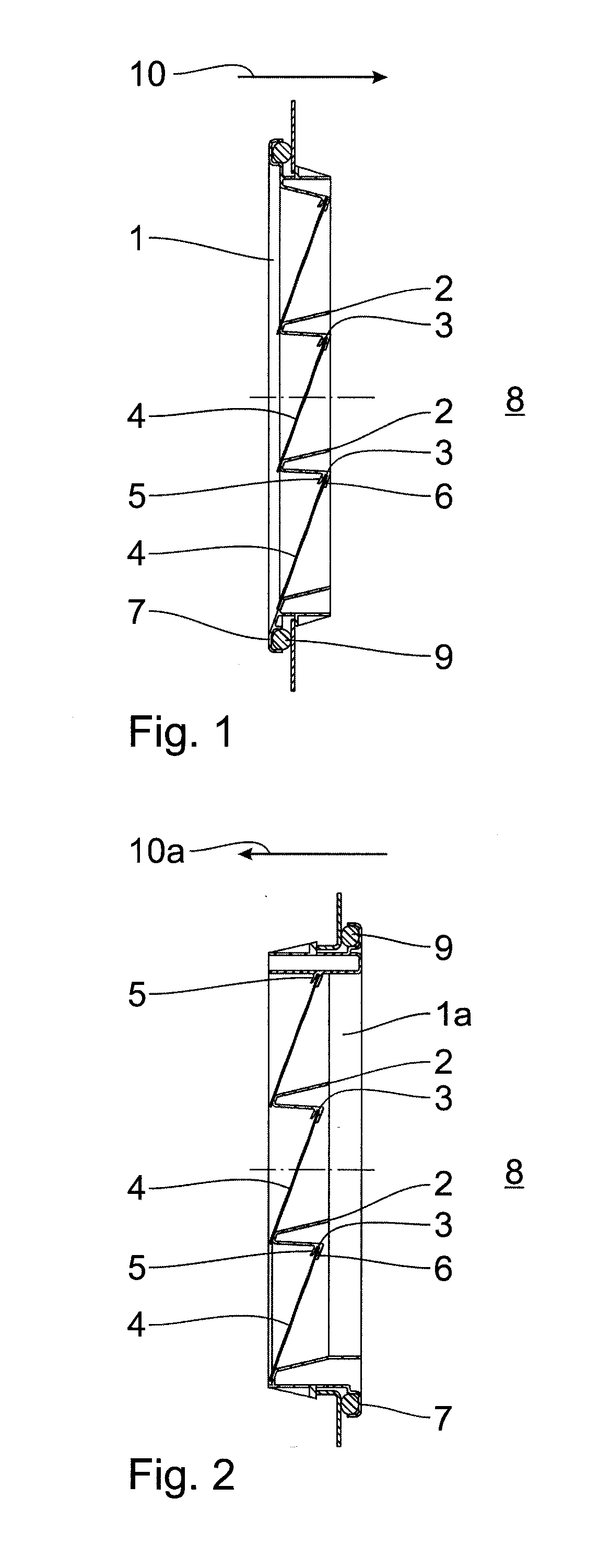
[0016]The ventilation flap arrangements shown in FIGS. 1 and 2 have a frame 1, 1a with a plurality of support ribs 2 and a plurality of receiving grooves 3 to hold cover flaps 4, each receiving groove 3 being formed by two side cheeks 5, which are moulded in one piece on the frame 1, 1a. For easier introduction of the cover flap 4 into the receiving groove 3, the side cheeks 5 may in each case have an insertion bevel oriented toward the receiving groove 3. The receiving groove 3 may comprise a plurality of reinforcement ribs 15 (cf. FIG. 6), which are moulded in one piece on the support rib 2 between the two side cheeks 5 in a groove base 6. The reinforcement ribs 15 are used to stabilise the receiving groove 3 formed by the side cheeks 5, so a possible distortion of the side cheeks 5 and therefore a shape deviation of the receiving groove 3 as a result of a previous production method, in particular an injection moulding process with a subsequent cooling process, are reduced. The fr...


PUM

PropertyMeasurementUnit
Temperatureaaaaaaaaaa
Dimensional stabilityaaaaaaaaaa
Flexibilityaaaaaaaaaa

Abstract

A ventilation flap arrangement, in particular for venting a motor vehicle interior, as well as a method for producing a ventilation flap arrangement of this type, which has the method steps of providing one or more flexible cover flaps, providing a frame for holding the cover flaps, wherein the frame for a cover flap has a receiving groove formed by two side cheeks, inserting the cover flap between the two side cheeks of the receiving groove of the frame and non-detachable connection of the cover flap to the receiving groove by embossing.

Description

FIELD OF THE INVENTION[0001]The invention relates to a ventilation flap arrangement, in particular for venting a motor vehicle interior, with cover flaps and a frame for holding the cover flaps. Furthermore, the invention relates to a method for producing a ventilation flap arrangement of this type.BACKGROUND OF THE INVENTION[0002]A ventilation flap arrangement with an inner frame, an outer housing and cover flaps is known from DE 40 02 052 A1, the cover flaps consisting of very soft, flexible material being clamped between the inner frame and the outer housing. A ventilation flap arrangement of this type is produced in a complex assembly process with many individual components.[0003]It is furthermore known from DE 195 48 551 A1 that cover flaps are produced in one piece with a frame by means of conventional two-component injection moulding methods. These production methods require expensive tools and optionally injection moulding machines adapted thereto. The production of a ventil...

Claims


Application Information

Patent Timeline
IPC IPC(8): B60H1/34B23P11/00
CPCY10T29/49826B60H1/249
Inventor JANSEN, HELGE
Owner EUWE EUGEN WEXLER HLDG GMBH & CO KG
Why Eureka
Try Eureka