MIMO communication device

a communication device and a technology of a communication device, applied in the direction of transmission monitoring, wireless communication services, polarised antenna unit combinations, etc., can solve the problems of system throughput decline, communication deterioration, and radio propagation communication channel state deterioration

Inactive Publication Date: 2010-05-13
PANASONIC CORP
View PDF14 Cites 25 Cited by
  • Summary
  • Abstract
  • Description
  • Claims
  • Application Information

AI Technical Summary

Benefits of technology

[0015]The present invention can provide a MIMO communication apparatus that can maintain characteristics of MIMO communication at or above a certain level regardless of the location to set the MIMO communication apparatus.

Problems solved by technology

Therefore, when there is a specific relationship between an arrangement of antennas in radio equipment and propagation environment of the surroundings of the radio equipment, there are cases where the state of the radio propagation communication channel deteriorates.
That is, there are cases where quality of MIMO communication deteriorates or the system throughput decreases.

Method used


Image

  • MIMO communication device
  • MIMO communication device
  • MIMO communication device

Examples


embodiment 1

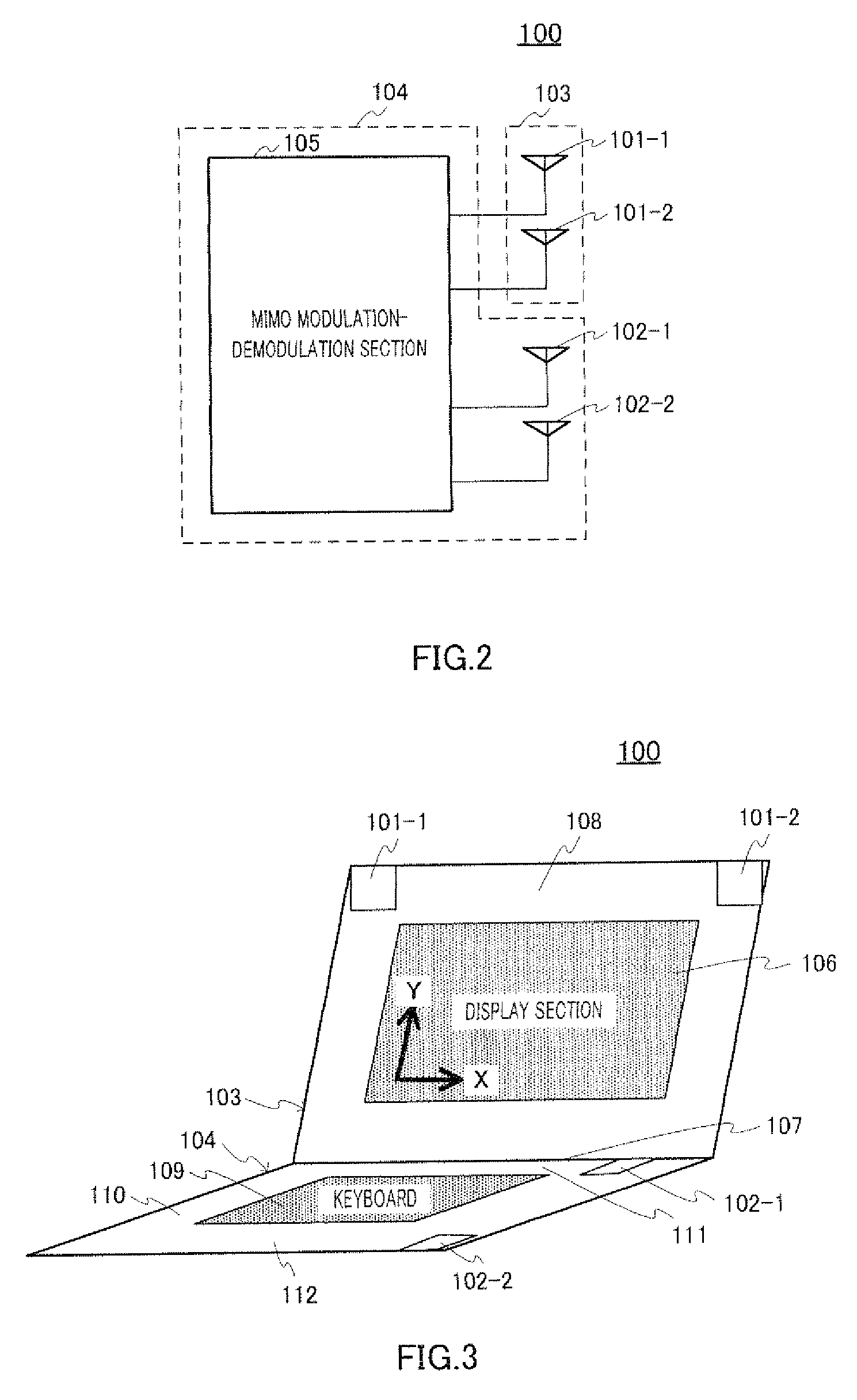
[0031]FIG. 2 is a block diagram showing the configuration of a MIMO communication apparatus according to Embodiment 1 of the present invention. MIMO communication apparatus 100 shown in the same figure has: antenna element 101-1 and antenna element 101-2 that are provided in locations on one straight line; antenna element 102-1 and antenna element 102-2 that are provided in locations apart from this straight line; and MIMO modulating section 105 that is connected with all of antenna elements (antenna element 101-1 and 101-2 and antenna element 102-1 and 102-2). MIMO communication apparatus 100 has first housing 103 and second housing 104.

[0032]First antenna element 101-1 and second antenna element 101-2 are provided in first housing 103. Further, third antenna element 102-1 and fourth antenna element 102-2 are provided in second housing 104.

[0033]In case where MIMO communication apparatus 100 is a portable personal computer (PC), the outlook of the portable PC is as shown in, for ex...

embodiment 2

[0107]FIG. 13 is a block diagram showing the configuration of the MIMO communication apparatus according to Embodiment 2 of the present invention.

[0108]As shown in the same figure, MIMO communication apparatus 1300 has antenna element 1301 that is provided on a straight line on which there are antenna element 101-1 and antenna element 101-2 in upper housing 103; and antenna element 1302 that is provided in lower housing 104. With Embodiment 2, antenna element 101-1, antenna element 101-2 and antenna elements 102 are the first polarized antenna elements. Antenna element 1301 and antenna element 1302 are the second polarized antenna elements different from the first polarized antenna elements. Further, MIMO modulation-demodulation section 105 is connected with all of antenna elements provided in MIMO communication apparatus 100.

[0109]In case where MIMO communication apparatus 1300 is a portable personal computer (PC), the outlook of this portable personal PC is as shown in, for exampl...


PUM


Abstract

Provided is a MIMO communication device which can maintain the MIMO communication characteristic at a certain level regardless of the device installation position. The MIMO communication device (100) includes antenna elements (101-1, 101-2) as a first and a second antenna element which are arranged on a single straight line and an antenna element (102-1) or an antenna element (102-2) as a third antenna element which is arranged out of the straight line. A MIMO modulation unit (105) is connected to all the antenna elements. This assures that there exists a combination of antennas having other than 0 as a matrix expression of a channel estimation matrix in a propagation path between the MIMO communication device (100) and the communication partner regardless of the installation position of the MIMO communication device (100) with respect to a communication partner. As a result, it is possible to realize the MIMO communication device which can maintain the MIMO communication characteristic at a certain level or above regardless of the device installation position.

Description

TECHNICAL FIELD[0001]The present invention relates to a MIMO communication apparatus.BACKGROUND ART[0002]In the field of radio communication equipment, MIMO (Multi-Input Multi-Output) communication, which uses array antennas, can increase the communication speed without expanding the frequency band in use, and improve the overall system throughput (see, for example, Non-Patent Document 1).[0003]Recently, in the field of wireless LAN, introduction of MIMO communication technology is being studied to standardize IEEE 802.11n, This technology is mentioned in the draft of the standard by IEEE in 2007. Similarly, MIMO communication technology is also being studied to increase the data transmission speed of mobile telephones, mobile wireless data terminals and so on.[0004]In a conventional wireless communication system not adopting MIMO communication technology, communication quality is determined by the electric field intensity in the receiving point. By contrast with this, in a communic...

Claims


Application Information

Patent Timeline
Patent Type & Authority Applications(United States)
IPC IPC(8): H04B1/38H01Q21/24H04B7/04H04J99/00
CPCH01Q1/2266H04B7/0413
Inventor FUKAGAWA, TAKASHINAKAGAWA, YOICHIUKENA, MASATO
Owner PANASONIC CORP
Why Eureka
Try Eureka