Universal double offset surgical instrument

a surgical instrument and double-offset technology, applied in the field of instruments, can solve the problems of muscle tissue, inability to access and prepare the femoral canal, and the proximal femoral intramedullary canal being exposed in order to achieve the effect of preparing the canal, and the instrument is physically large and heavy

Inactive Publication Date: 2010-05-13
SMITH & NEPHEW INC
View PDF98 Cites 62 Cited by
  • Summary
  • Abstract
  • Description
  • Claims
  • Application Information

AI Technical Summary

Problems solved by technology

Exposure of the proximal femoral intramedullary canal in order to prepare the canal to receive the femoral stem can be problematic in such anterior approach THA's, however.
Anatomical features of some patients, such as gut or muscle tissue, can nevertheless present problems in accessing and preparing the femoral canal through the smaller incision.
Such instruments are physically large and heavy however, and separate instruments are required for each of the right and left femurs in order to provide the required lateral offset.
Consequent issues include those related to, among other things, logistics, inventory requirement, and expense.

Method used


Image

  • Universal double offset surgical instrument
  • Universal double offset surgical instrument
  • Universal double offset surgical instrument

Examples


first embodiment

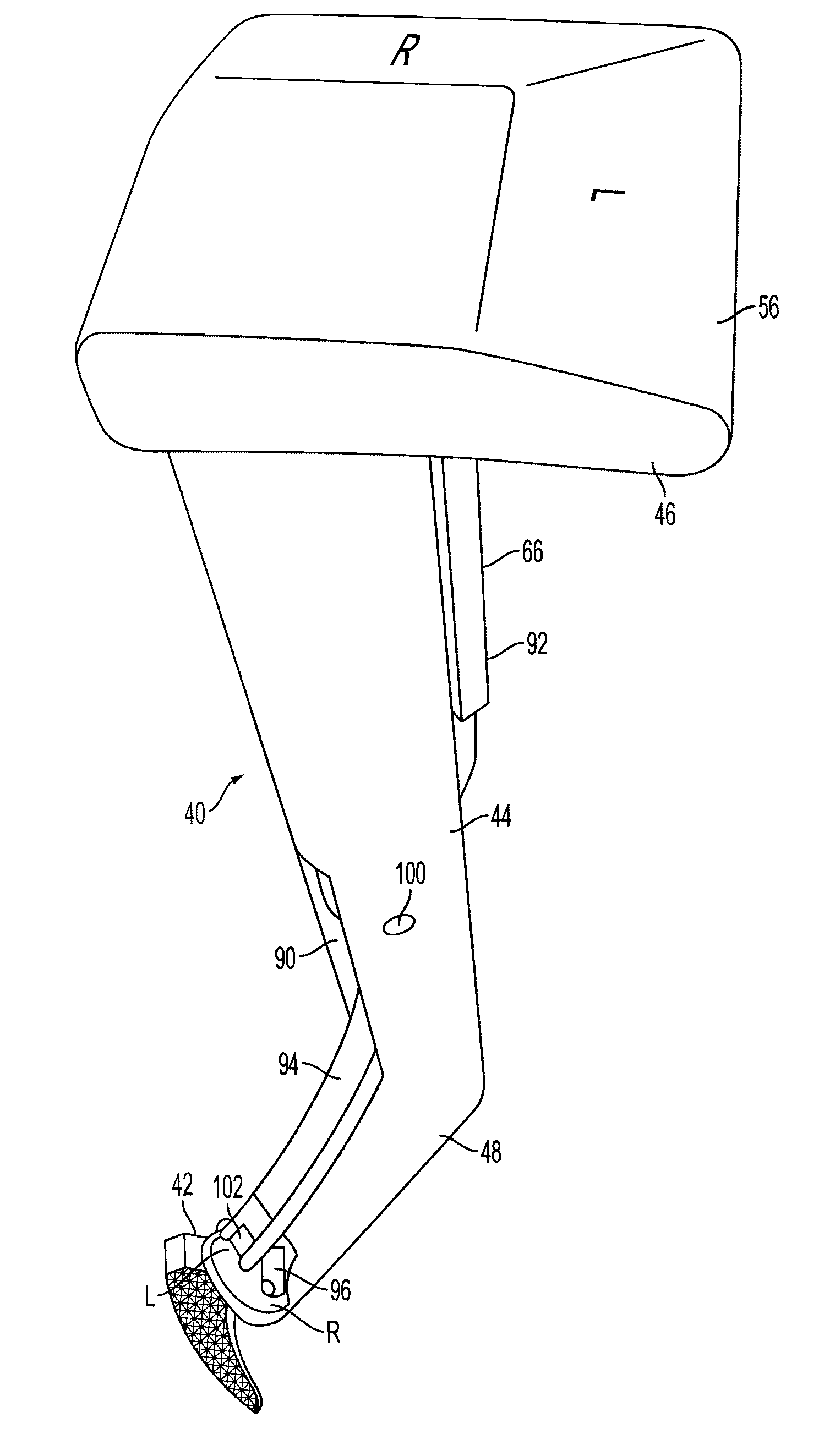
[0170]FIGS. 6 and 7 show an instrument 40 according to the present invention that can be used to prepare the intramedullary canal of either or both a left or right femur for total hip replacement or other hip surgery. Instrument 40 shown in FIGS. 6 and 7 connects to, and can be considered to include when assembled, a shaping member 42. FIGS. 6 and 7 show the shaping member 42 in the form of a broach but any shaping member such as a reamer, osteotome, sawblade, graft impaction member, broach or other device configured to prepare the intramedullary canal of a bone can be used as a shaping member 42. It should be noted that instead of a shaping member 42, instrument 40 may be advantageously configured to allow insertion of an intramedullary implant such as a femoral stem, for instance, through the use of an adaptor or otherwise. Instrument 40 may be formed of any desired material with appropriate strength, manufacturability, autoclavability, cost, and other desired performance factors....

third embodiment

[0202]FIGS. 38A-38C show an instrument 440 according to the invention. There, a handle 444 is slideably connected to a first offset 448(a) which in turn connects to a second offset 448(b). The sliding engagement between the handle 444 and first offset 448(a) may be facilitated by a track 450 having means 468 for fixing the handle 444 to the first offset 448(a), such as a set screw or spring-loaded latching button. The first offset 448(a) and second offset 448(b) help align the longitudinal axis 468 of shaping member 442 to be essentially parallel with longitudinal axis 454 of handle 444. First offset 448(a) slides relative to handle 444 in order to provide the lateral offset desired for left or right femur. Either or both first offset 448(a) or second offset 448(b) can extend in a direction that includes the posterior or negative Y component in order to provide the desired anterior offset of handle 444 relative to shaping member 442. Second offset 448(b) may be provided with adjustm...

fourth embodiment

[0203]FIG. 39 shows an instrument 540 according to the present invention. There, handle 544 is connected in pivoting fashion to an offset 548 that pivots or swivels relative to the longitudinal axis 554 of handle 544. Offset 548 extends in a direction that includes an X directional component and a negative Y or posterior directional component. When the offset 548, handle 544, and shaping member 542 are swiveled to a first position, it provides desired lateral and anterior offset of handle 544 relative to shaping member 542 to accommodate a first leg. When the offset 548, handle 544, and shaping member 542 are pivoted and locked in the other position, it provides desired lateral and anterior offset to accommodate the other leg. Again, the pivoting connection between handle 544 and offset 548 can be constructed as desired with suitable locking mechanism, and the shaping member 542 can be connected to offset 548 with interconnection structure 560 as desired.


PUM


Abstract

Instruments for use in anterior approach total hip arthroplasty. Instruments according to certain embodiments of the invention connect to a shaping member such as a broach, reamer or osteotome that is used to prepare the intramedullary canal of a desired femur or other bone for total hip arthroplasty. Such an instrument according to such embodiments can be configurable to allow operation on either the left or right leg, and in doing so to provide lateral offset and anterior offset of the instrument handle relative to the shaping member so that the patient's gut, musculature or other bodily portions may be avoided while still providing desired leverage and control over the shaping member to prepare the intramedullary canal.

Description

CROSS-REFERENCE TO RELATED APPLICATIONS[0001]This application is a continuation-in-part application of U.S. application Ser. No. 12 / 412,527 filed Apr. 27, 2009 entitled, “Surgical Technique and Instrumentation for Minimal Incision Hip Arthroplasty,” which is a continuation application of U.S. application Ser. No. 10 / 991,641 filed Nov. 18, 2004 entitled, “Surgical Technique and Instrumentation for Minimal Incision Hip Arthroplasty” and which issued on Sep. 22, 2009 as U.S. Pat. No. 7,591,821, which claims priority to U.S. Application Ser. No. 60 / 520,970 filed Nov. 18, 2003 entitled “Surgical Technique and Instrumentation for Minimal Hip Arthroplasty,” all of which are incorporated herein by this reference.STATEMENT REGARDING FEDERALLY SPONSORED RESEARCH OR DEVELOPMENT[0002]Not Applicable.APPENDIX[0003]Not Applicable.BACKGROUND OF THE INVENTION[0004]1. Field of the Invention[0005]Embodiments of the invention relate generally to instruments for use in orthopedic surgery, and more parti...

Claims


Application Information

Patent Timeline
Patent Type & Authority Applications(United States)
IPC IPC(8): A61B17/16
CPCA61B17/00234A61B17/1604A61B17/1659A61B17/1668A61B17/164A61B2017/0046A61F2/4607A61F2/4657A61F2002/4635A61B19/5244A61B34/20
Inventor SHARP, JEFFREY A.GIBSON, LUKE A.KELMAN, DAVID C.
Owner SMITH & NEPHEW INC
Why Eureka
Try Eureka