
Learing method of rolling load prediction for hot rolling

a learning method and rolling load technology, applied in adaptive control, shaping safety devices, instruments, etc., can solve the problems of easy dispersal, inability to predict the actual pass of rolling load, and the trend of rolling load prediction error is not always constant, so as to and improve the accuracy of rolling load prediction

Active Publication Date: 2010-05-13
NIPPON STEEL CORP
View PDF13 Cites 26 Cited by
  • Summary
  • Abstract
  • Description
  • Claims
  • Application Information

AI Technical Summary

Benefits of technology

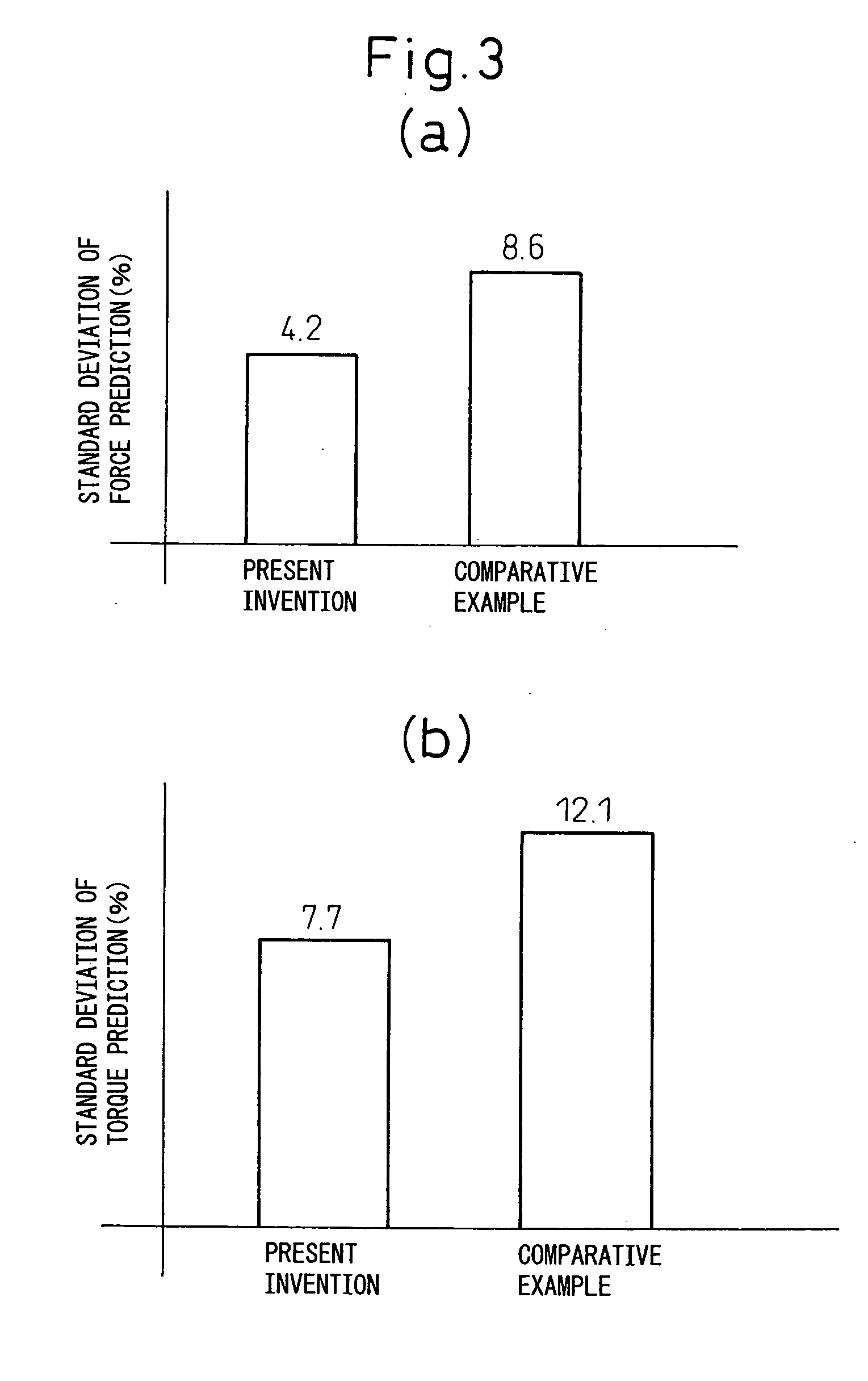
[0030]According to the aspect of the invention of the above (I), compared with the prior art, learning in rolling load prediction can be realized enabling an improvement of the precision of the rolling load prediction in hot rolling.
[0031]Furthermore, according to the aspect of the invention of the above (II), learning in rolling load prediction can be realized enabling stable improvement of the precision of the rolling load prediction.
[0032]Further, according to the aspects of the invention of the above (III) to (VI), furthermore learning in rolling load prediction can be realized enabling stable improvement of the precision of the rolling load prediction.
[0033]In addition, according to the aspect of the invention of the above (VII), the precision of the rolling force prediction can be stably improved, so it is possible to precisely estimate the mill stretch, roll deflection, and other elastic deformation of the rolling mill, set the roll gap and crown control amount so as to compensate for this, and thereby improve the precision of thickness, crown, and flatness of the stock.
[0034]Further, according to the aspect of the invention of the above (VIII), the precision of the rolling force prediction can be stably improved, so it is possible to precisely estimate the power, set the rolling speed so that this satisfies an allowable range and thereby improve the productivity.
[0035]In the above way, according to the present invention, in hot rolling, it is possible to more stably improve the precision of the rolling load prediction compared with the past. Further, due to this, it is possible to make the thickness, crown, and flatness of the rolled products closer to the desired values, so the effects are also obtained that the yield loss in rolling is suppressed and the productivity is improved.

Problems solved by technology

At this time, a prediction formula using the components, dimensions, temperature, rolling conditions, etc. of the stock as parameters is used so as to predict the rolling load, but error in prediction of the rolling load sometimes occurs due to the low precision of the prediction formula used and error between the settings (predicted values) of the parameters inputted into the prediction formula and the actual values.
In this regard, in general, the trend in prediction error of the rolling load in actual passes is not always constant for different passes even for the same stock.
At this time, if making the gain α excessively large, the prediction error will tend to easily disperse, while if making the gain a excessively small, the prediction error of the rolling load will be harder to converge.
However, in general, the prediction error of the rolling load at an actual pass is distributed over a wide range, so with the method of adjusting the gain α to be multiplied with the error of the rolling load prediction in an actual pass in accordance with the error from the average value of the past results of the prediction error of the rolling load at an actual pass so as to set the learning coefficient CF of the rolling force prediction at the predicted pass, it is difficult to stably raise the precision of the rolling load prediction.
However, the error factors of the rolling load include various factors such as the surface conditions of the stock and rolling rolls, the temperature and deformation characteristics of the stock, the precision of setting the rolling conditions, etc.
It is extremely difficult to logically extract and estimate error of this large number of influencing factors.

Method used


Image

  • Learing method of rolling load prediction for hot rolling
  • Learing method of rolling load prediction for hot rolling
  • Learing method of rolling load prediction for hot rolling

Examples


example 1

[0056]Below, an example of the present invention will be explained based on the drawings. Note that, the numerical values, functions, etc. used in the following examples are nothing more than illustrations for explaining the present invention. The present invention is not limited to the following examples. Note that component elements having substantially the same functional configurations in the Description and Drawings are assigned the same reference signs and overlapping explanations are omitted.

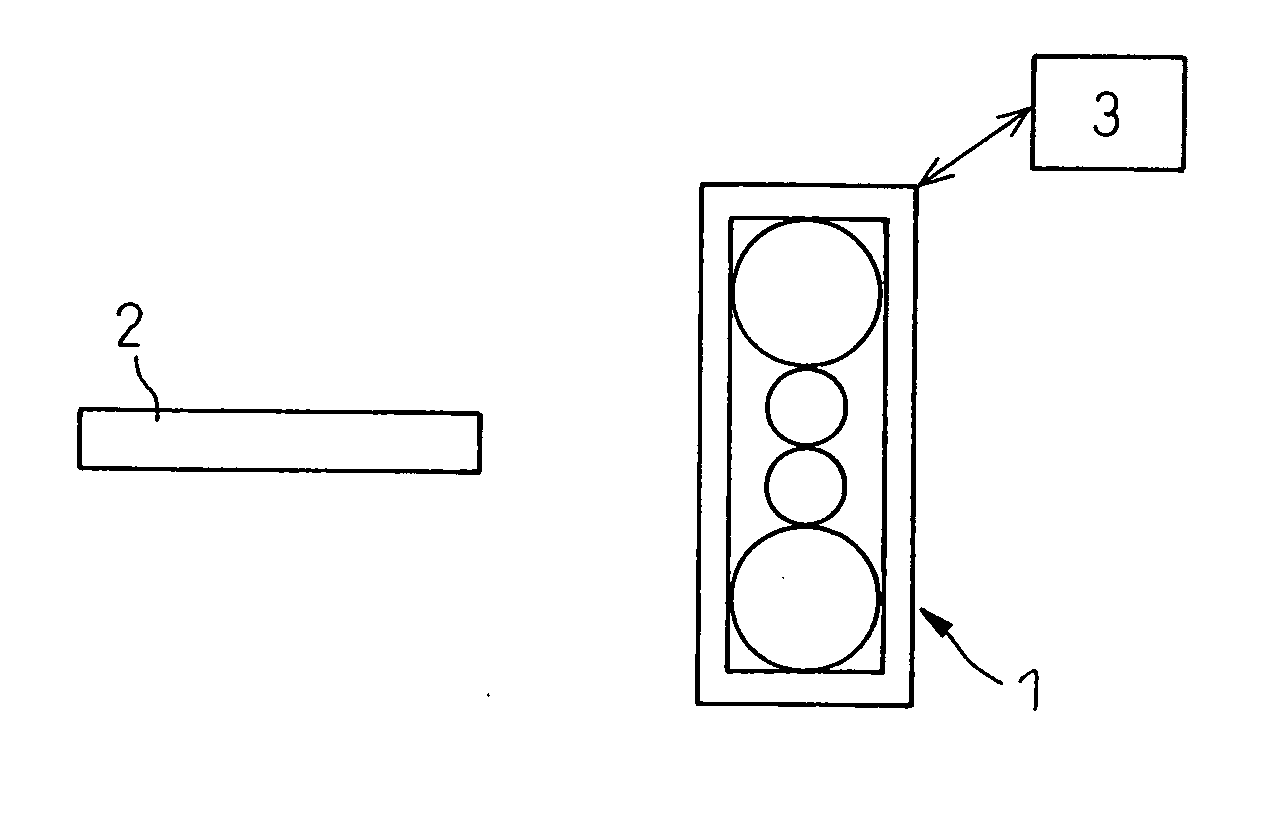
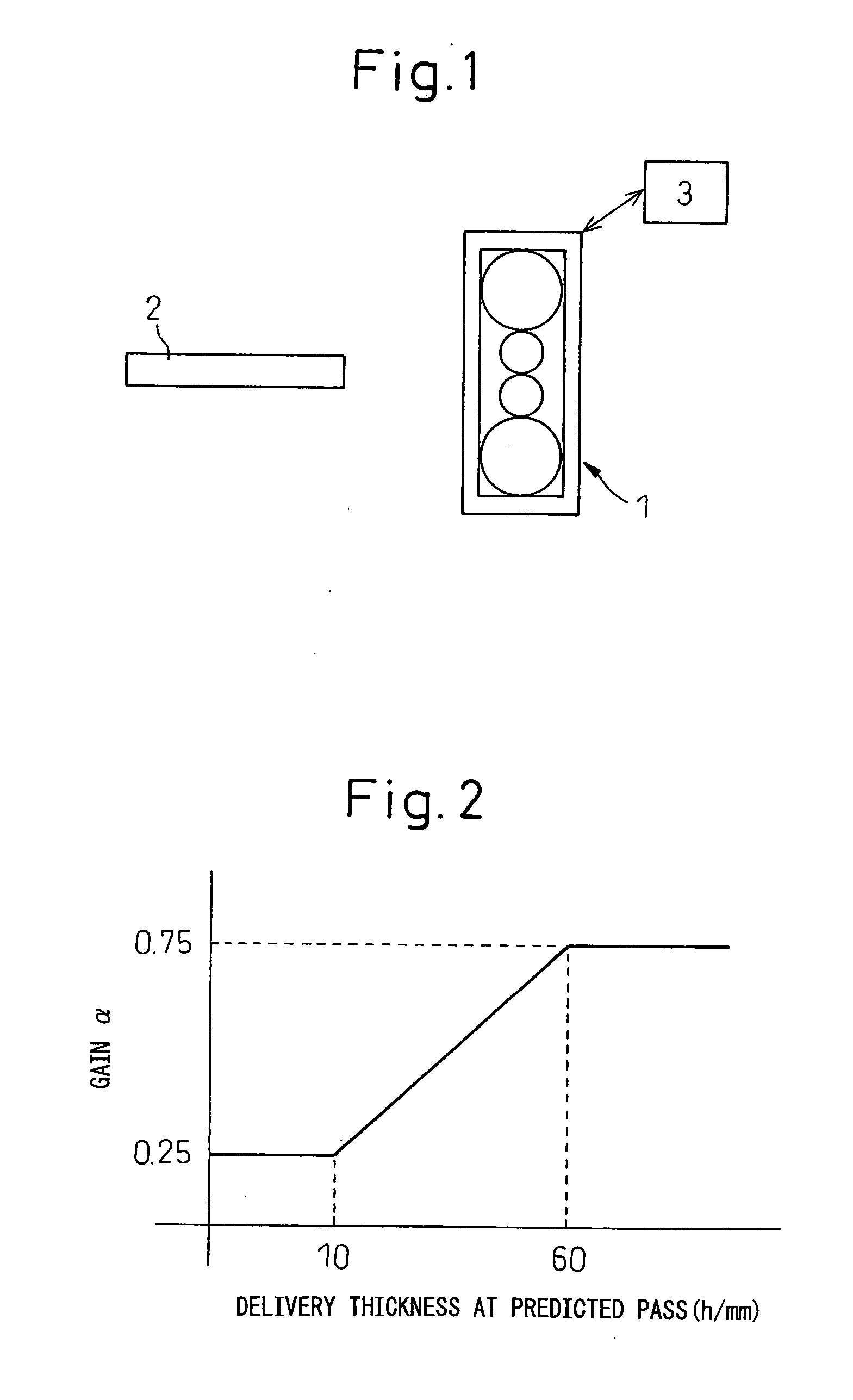
[0057]Consider an example applying the present invention to inter-pass learning for rolling force prediction and rolling torque prediction in reverse multi-pass type rolling by a rolling mill 1 shown in FIG. 1. In the rolling mill 1, the stock 2 has already been rolled by an (i−1)-th pass and is about to be rolled at an i-th pass. At this time, the rolling force Pexpi-1 and rolling torque Gexpi-1 at the (i−1)-th pass and the entry thickness Hi-1, the delivery thickness hi-1, and the rolli...

example 2

[0076]Example 2, like Example 1, applies the present invention to inter-pass learning of rolling force prediction in reverse type multi-pass rolling by the rolling mill 1 shown in FIG. 1. In the present example, as shown in formula (7), the gain α was changed in accordance with the referred to the delivery thickness h at the actual pass.

α={0.2(h10)0.3(10≤h15)0.4(15≤h30)0.5(30≤h50)0.6(50≤h75)0.7(75≤h100)0.8(100≤h)(7)

[0077]Note that, the relationship between the delivery thickness h at the actual pass and gain α based on formula (7) is shown in FIG. 4 as well. Further, at each rolling pass, the learning coefficient at the rolling force prediction at the following rolling passes was updated so as to correct the draft schedule and crown control amount at the subsequent passes. In this way, a hot steel plates were rolled with initial thickness of 40.0 to 200.0 mm, delivery thickness at the final pass of 4.0 to 150.0 mm, a width of 1200 to 4800 mm, and a total number of rolling passes of ...

example 3

[0082]Example 3 is an example of application of the present art to a tandem rolling process of hot strip with a final stand delivery thickness of 1.0 to 20.0 mm.

[0083]As shown in FIG. 8, consider the example of application of the present invention to inter-pass learning of rolling force prediction in tandem rolling in a group of rolling mills 4 comprised of five rolling mills 4a to 4e. In the group of rolling mills 4, the stock 2 is already rolled by the first stand 4a and is about to be rolled by the second stand 4b to the fifth stand 4e. At this time, the rolling force Pexp1 at the first stand, the entry thickness H1 of the stock 2, the delivery thickness h1, and the rolling temperature T1 are stored in the processing unit 3. Further, the processing unit 3 also stores the work roll radius R of the stands 4a to 4e of the group of rolling mills 4 and the material components and width w of the stock 2.

[0084]Here, it may be considered to use the prediction error of rolling force at th...


PUM

PropertyMeasurementUnit
widthaaaaaaaaaa
widthaaaaaaaaaa
thicknessaaaaaaaaaa

Abstract

In the learning method of rolling load prediction in hot rolling, in the past the prediction error of the rolling load was corrected based on envisioned error factors, but in the complicated rolling phenomenon, there are many influential factors and therefore logical extraction and estimation had been difficult.Therefore, the learning method of rolling load prediction according to the present invention refers to prediction error of a rolling load at an actual pass of a stock in hot rolling to correct a predicted value of rolling load at a rolling pass to be performed from then on, at which time changing a gain multiplied with the prediction error of the rolling load at said actual pass in accordance with a thickness of said stock to thereby set the learning coefficient of the rolling load prediction and improve the precision of the prediction.

Description

TECHNICAL FIELD[0001]The present invention relates to a learning method of rolling load prediction for hot rolling.BACKGROUND ART[0002]When rolling a stock to a desired thickness, in general two or more rolling passes are used to obtain the thickness of the rolled material close to the desired thickness. At this time, a target value of the delivery thickness at each pass is given and the rolling force, rolling torque, and other rolling load at each pass when achieving this are predicted. Furthermore, it is becoming necessary to estimate the mill stretch, roll deflection, and other elastic deformation amounts of the rolling mill based on these predicted values and set the roll gaps and crown control amounts so as to compensate for these and to estimate the power and set the rolling speed so that these satisfy allowable ranges, then perform the rolling.[0003]At this time, a prediction formula using the components, dimensions, temperature, rolling conditions, etc. of the stock as param...

Claims


Application Information

Patent Timeline
Patent Type & Authority Applications(United States)
IPC IPC(8): B21B37/00G05B13/04
CPCB21B2261/04B21B2275/12B21B37/58B21B37/00B21B2265/12B21B37/16
Inventor HIGO, TSUYOSHIMIZOGUCHI, YOSUKEIGARASHI, KAZUTSUGUFUKUOKA, YASUSHI
Owner NIPPON STEEL CORP
Learn More