Robot and robot system

Inactive Publication Date: 2010-05-13
SEIKO EPSON CORP
View PDF11 Cites 15 Cited by
  • Summary
  • Abstract
  • Description
  • Claims
  • Application Information

AI Technical Summary

Benefits of technology

[0024]According to the robot system, the distance between the transmitter and the receiver is measured using the ultrasonic waves. Compared with a propagation velocity of electromagnetic waves such as light and radio waves, a propagation velocit

Problems solved by technology

In a case where each robot is autonomously operated,

Method used


Image

  • Robot and robot system
  • Robot and robot system
  • Robot and robot system

Examples


Example

[0038]Hereinafter, an embodiment of the invention will be described with reference to the accompanying drawings. The scales of members in the drawing are adequately changed so that they can be recognized.

Embodiment

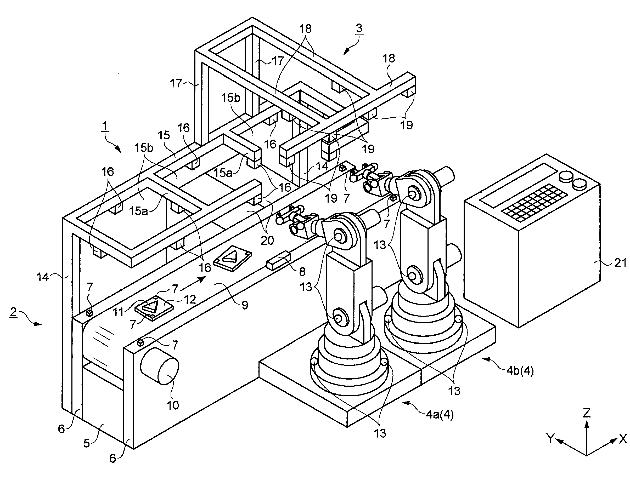
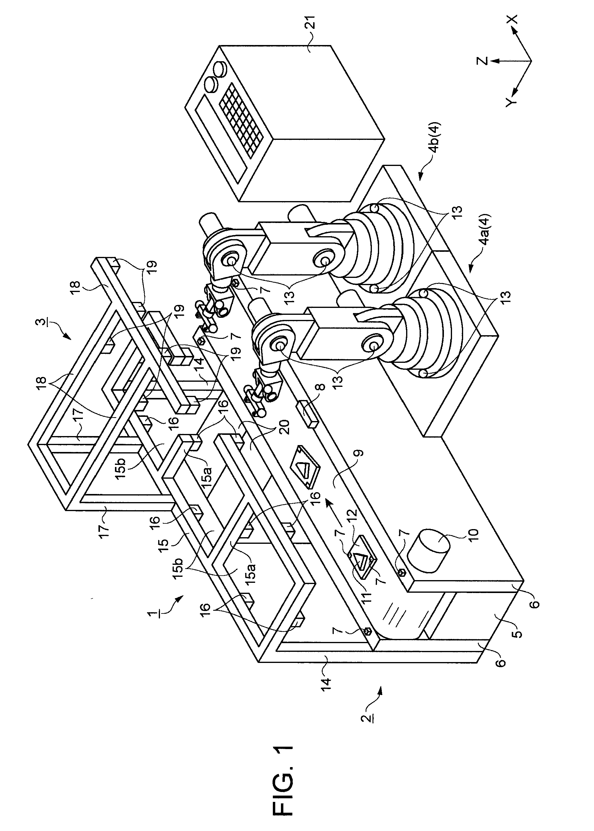
[0039]A robot, a robot system, and a method for controlling the robot according to the embodiment will be described with reference to FIGS. 1 to 10C. The method for controlling the robot will be described using an example. In the example, two robots move while respectively gripping a workpiece. The robots release the workpiece, so that the workpiece is moved.

[0040]FIG. 1 is a perspective view schematically showing a structure of the robot system. As shown in FIG. 1, a robot system 1 mainly includes a conveyor device 2 serving as a conveyer, a position detecting unit 3, and a robot 4. The conveyor device 2 includes a base 5 formed long in one direction. A longitudinal direction of the base 5 is referred to as an X direction. A direction opposite to the gravity direction is ...


PUM


Abstract

A robot system includes a robot including a movable portion, a plurality of transmitters that is provided on the movable portion and transmits wireless signals, three or more receivers receiving the wireless signals transmitted from each of the transmitters, and a position calculating unit detecting locations of the transmitters based on the wireless signals that the plurality of the receivers receives. In the system, the position calculating unit detects a pose of the robot from information on the locations of the detected plurality of the transmitters.

Description

BACKGROUND[0001]1. Technical Field[0002]The present invention relates to a robot, a robot system, and the like. The invention especially relates to position detection of a movable portion of the robot.[0003]2. Related Art[0004]Manufacturing apparatuses using a plurality of robots are widely used to automate tasks. In general, the robots are programmed so as to operate in synchronization with an operation of each robot. Thus, the robots do not collide with each other. In a case where each robot is autonomously operated, it potentially results in a collision with each other. A method for preventing the collision between the robots is disclosed in JP-A-2004-280635. In the method, the collision is prevented by simulating operations of each robot. According to the method, a plurality of models of the robot is formed in a computer so as to presume a transition of major points forming the models. Subsequently, it is examined that whether or not the robot models interfere with each other. I...

Claims


Application Information

Patent Timeline
IPC IPC(8): G05B19/00G06F19/00B25J13/08
CPCG05B19/402G05B2219/40554G05B2219/39102
Inventor INAZUMI, MITSUHIRONAGATE, TAKASHI
Owner SEIKO EPSON CORP
Why Eureka
Try Eureka