
Method and system for diagnostics of apparatus

a diagnostic system and apparatus technology, applied in the field of diagnostic and monitoring systems, can solve the problems of nonlinear fault estimation problems, linear models and methods cannot adequately address multivariable diagnostic estimation problems, false positives and false negatives, etc., to improve apparatus performance, improve apparatus operation safety, and solve the effect of efficient solution

Active Publication Date: 2010-05-13
MITEK ANALYTICS
View PDF22 Cites 60 Cited by
  • Summary
  • Abstract
  • Description
  • Claims
  • Application Information

AI Technical Summary

Benefits of technology

[0009]An embodiment of the invention addresses the problem of integrated multivariable diagnostics by proposing a new method that includes optimization-based approach for diagnostic estimation. Multivariable diagnostic estimation problems are hard computationally and analytically because of nonlinearity and discrete nature of faults; this invention teaches a method for diagnostics estimation that overcomes the difficulties. The proposed method is rigorous; it has superior sensitivity, accuracy, conceptual simplicity, and computational performance compared to the prior art multivariable diagnostic methods.
[0010]It is an aspect of the present invention to provide a method for diagnostic estimation of fault states of an apparatus. The proposed fault diagnostics method is preferably implemented in software and can be adapted to work with different types of applications (faults, apparatuses, and systems) by changing initial data processing step of the method, fault signatures used in the method, and other configurable parts of the method. The method performs apparatus monitoring and for that purpose it is intended to execute repeatedly and periodically after obtaining additional data from the sensors attached to the apparatus or its environment. The advantages of the proposed method that will become clear from the detailed description set forth below include accuracy, computational efficiency, conceptual clarity, implementation convenience, and maintainability after initial implementation has been completed.
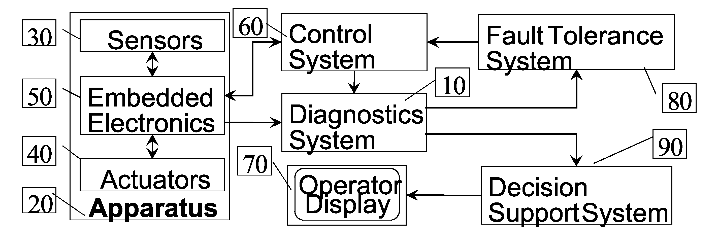
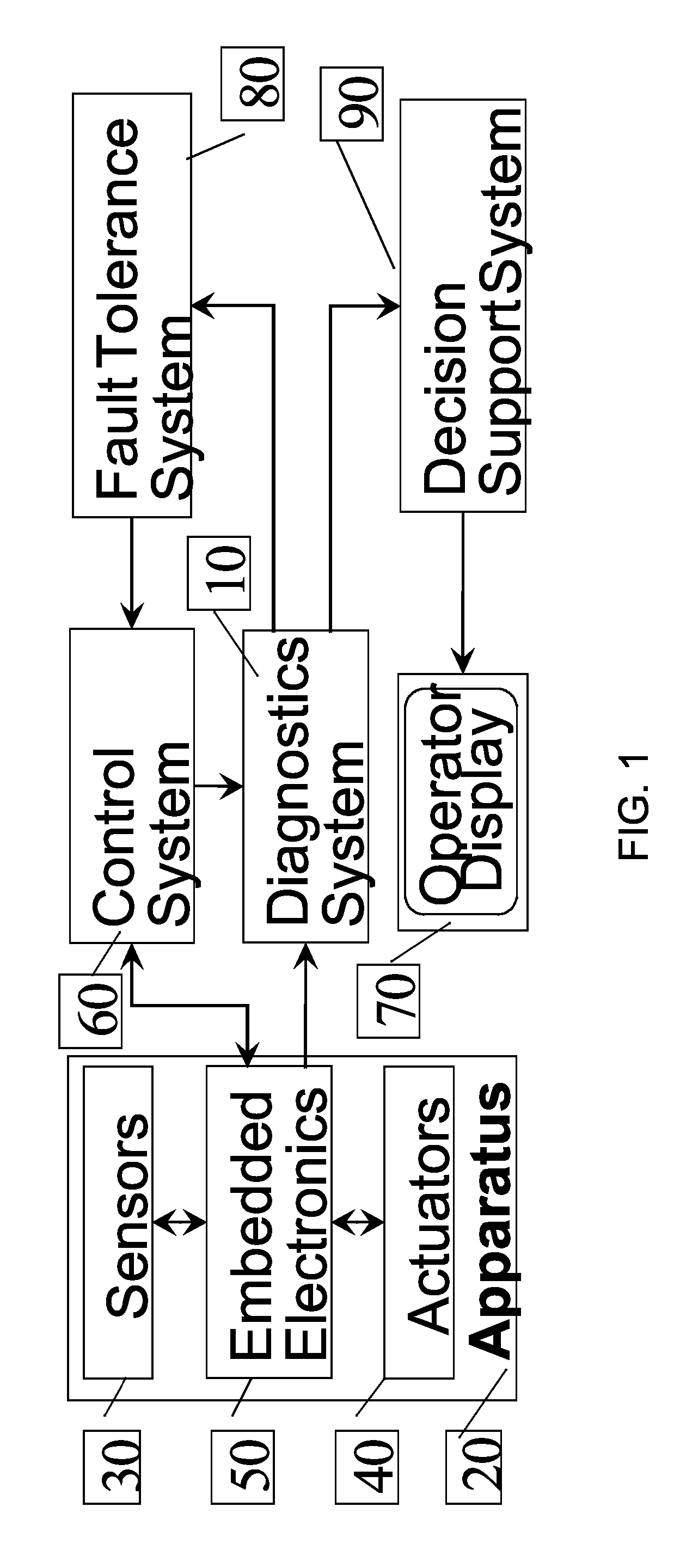
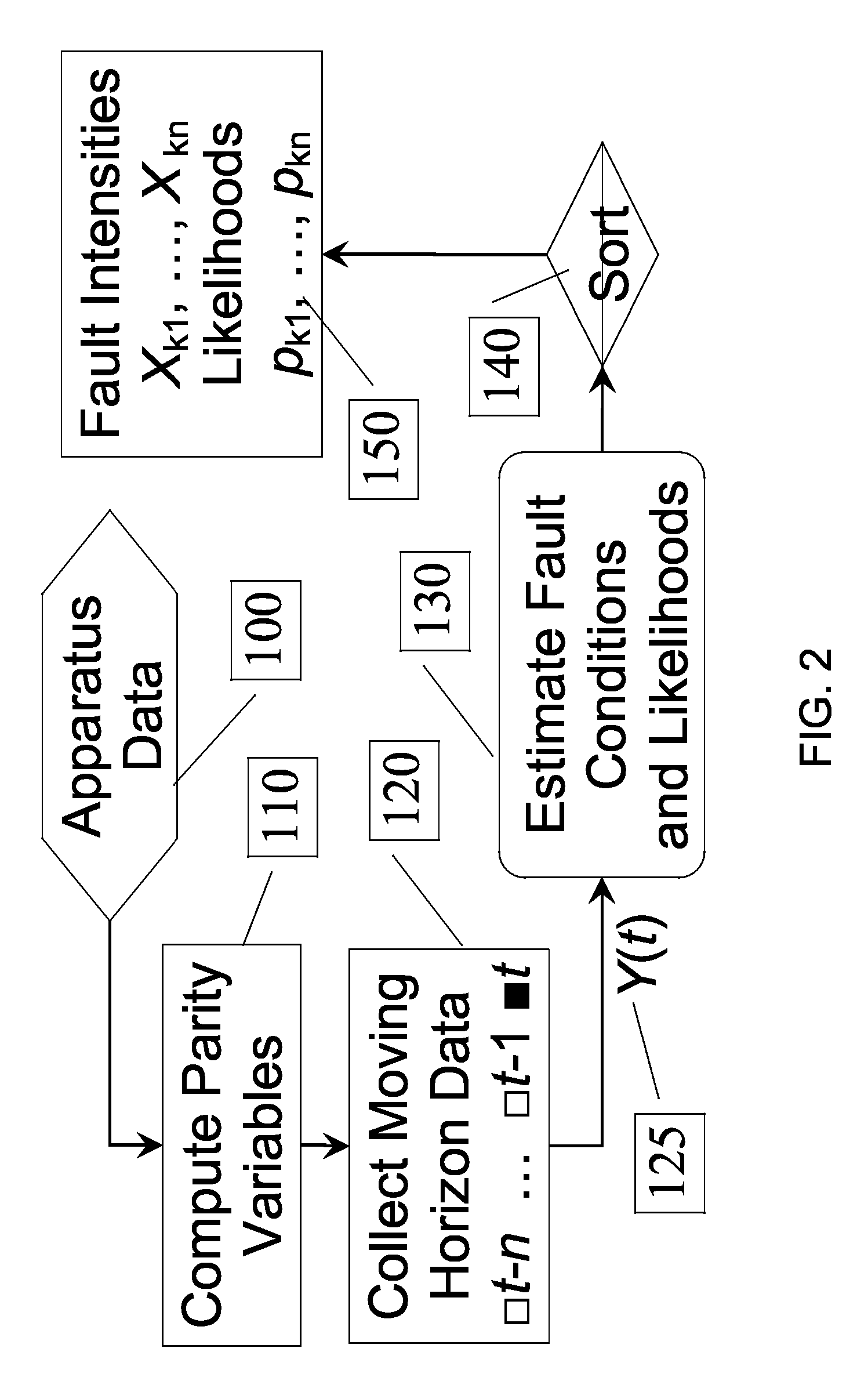
[0016]The diagnostic estimates for faults obtained at Step 3 and used at Step 4 comprise estimates of fault condition intensity parameters xk(t) over the moving horizon interval of time computed as the optimal solution and likelihood parameters pk computed as the optimum value of the program. The fault condition parameters xk(t) and likelihood parameters pk computed by the optimizer can be used for determining one or several most likely candidate fault conditions (by sorting the likelihoods) and intensities of these conditions. This information can be employed for improving safety of the apparatus operation by halting or reconfiguring the operation in an event of the fault. The reconfiguration can be also used for improving apparatus performance. Alternatively, knowing which fault might have most likely occurred can be used for scheduling a correct maintenance action with reduced troubleshooting effort.
[0020]i. A convex program formulated by the formulator and solved by the optimizer is guaranteed to have a single global solution that can be efficiently computed.

Problems solved by technology

The linear models and methods cannot adequately address the multivariable diagnostic estimation problems because they cannot deal with nonlinearities, constraints, and system structure changes.
The MHE or a related optimization based approach can be used for multivariable diagnostics estimation, but there are two difficulties that need to be overcome.
One difficulty is that the fault estimation problems are nonlinear.
Another difficulty is that these problems include discrete variables that describe the presence or absence of faults.
Incorrect estimation of these discrete variables could lead to false positives and false negatives in the fault detection; both types of errors are undesirable.
Presence of the discrete variables could lead to combinatorial complexity of the problem.
Besides being inherently suboptimal in dealing with the combinatorial complexity, these methods are slow and, thus, not suitable for real time use in an embedded system or for centralized data processing for a large fleet of monitored devices (e.g., monitoring a fleet of engines).

Method used


Image

  • Method and system for diagnostics of apparatus
  • Method and system for diagnostics of apparatus
  • Method and system for diagnostics of apparatus

Examples


Embodiment Construction

[0043]In the following detailed description, reference will be made to the accompanying drawing(s), in which identical functional elements are designated with like numerals. The aforementioned accompanying drawings show by way of illustration, and not by way of limitation, specific embodiments and implementations consistent with principles of the present invention. These implementations are described in sufficient detail to enable those skilled in the art to practice the invention and it is to be understood that other implementations may be utilized and that structural changes and / or substitutions of various elements may be made without departing from the scope and spirit of present invention. The following detailed description is, therefore, not to be construed in a limited sense. Additionally, the various embodiments of the invention as described may be implemented in the form of software running on a general purpose computer, in the form of a specialized hardware, or combination ...


PUM


Abstract

Proposed is a method, implemented in software, for estimating fault state of an apparatus outfitted with sensors. At each execution period the method processes sensor data from the apparatus to obtain a set of parity parameters, which are further used for estimating fault state. The estimation method formulates a convex optimization problem for each fault hypothesis and employs a convex solver to compute fault parameter estimates and fault likelihoods for each fault hypothesis. The highest likelihoods and corresponding parameter estimates are transmitted to a display device or an automated decision and control system. The obtained accurate estimate of fault state can be used to improve safety, performance, or maintenance processes for the apparatus.

Description

FIELD OF THE INVENTION[0001]The present invention is related generally to diagnostic and monitoring systems wherein there is a combination of computing device, which implements a computational method for diagnostics and a device or apparatus diagnosed and monitored thereby. “Apparatus” here may include a machine, an industrial plant, a vehicle, manufacturing process, facility, utility system, or other engineered system. “Diagnostics” here is defined as determining whether an apparatus is operating normally and, if not, determining more detained information about the fault or failure experienced by the apparatus from the available data.BACKGROUND OF THE INVENTION[0002]Modern apparatuses such as aerospace or ground vehicles, propulsion systems, electrical power systems, industrial equipment and machines, etc are outfitted with sensors and digital processors for control and monitoring of the apparatuses. Diagnostics functions are control and monitoring functions that have to do with an...

Claims


Application Information

Patent Timeline
IPC IPC(8): G06F15/00
CPCG05B23/0281
Inventor GORINEVSKY, DIMITRY
Owner MITEK ANALYTICS
Learn More