Method and device for melting the ends of rods

a technology of melting end and glass rod, which is applied in the direction of glass tempering apparatus, glass making apparatus, manufacturing tools, etc., can solve the problems of reducing stability, affecting the melting process, and insufficient melting of rod ends, so as to facilitate the lifting of glass rods, facilitate the flame treatment of the end of glass rod, and facilitate the effect of regulating the burner

Active Publication Date: 2010-05-20
SCHOTT AG
View PDF3 Cites 3 Cited by
  • Summary
  • Abstract
  • Description
  • Claims
  • Application Information

AI Technical Summary

Benefits of technology

[0007]An advancing device can comprise, in particular, a suitable conveyor belt on which the carrier is placed. Such a conveying mechanism also easily permits various kinds of carriers for various rod dimensions to be conveyed.
[0009]The invention makes available a very simple arrangement with which uniform post-processing of the ends of the glass rods is brought about. The rolling of the glass rods during the melting in the flame brings about uniform heating of the ends of the glass rods. The melting in particular also provides a smooth, fire-polished surface.
[0017]In one development of the invention, a heating device for the carrier is also provided. The carrier can particularly advantageously be preheated with such a heating device. In particular, this preheating of the carrier can be carried out with glass rods inserted. As a result, the parts of the glass rods which rest on the carrier are also preheated. This is favorable, inter alia, in order to avoid sudden transitions in the glass rods as a result of excessively high temperature change stresses. A particular advantage is obtained particularly when treating glass tubes. Heating the glass tubes on the carrier prevents deposition of condensates within the tubes when they are carried past the burner. The preheating is preferably carried out in multiple stages. In particular, it is possible for this purpose to place the glass rods on a carrier which is preheated in a first preheating step and to further preheat carriers with glass rods in at least one further step before the melting process.
[0022]Furthermore it is particularly advantageous if the rail is arranged between the carrier and burner openings. In this way, the rail can simultaneously act as a shield which prevents the burner carrying out flame treatment on other parts of the glass rods apart from their ends. In addition to one or more rolling bars on which the glass rods are made to rotate by rolling on their upper side, it is furthermore also advantageous to provide a run-up bar which runs in the advancing direction. With this run-up bar, the position of the glass rods which are carried past is aligned or arranged transversely with respect to the advancing direction. In order to facilitate the lifting of the glass rods at the start of the rail, the rail is furthermore preferably beveled at least one end in the advancing direction. Both ends of the rail are preferably beveled so that the glass rods do not drop back abruptly into the receptacles after rolling on the upper side but rather are positioned completely in the receptacles again after rolling slowly on the oblique surface.
[0023]In terms of the burner, it is also preferred that the combustible gas is not mixed in the nozzles of the burner but rather outside the nozzles in a mixer. The latter is preferably arranged upstream of a gas quantity regulator so that the combustible gas together with the oxidation agent which it contains is preferably regulated by air added by the mixer. This measure has surprisingly proven very favorable in obtaining a more simple way of regulating the burner. In particular, even very low overpressures can then be regulated precisely in order to bring about uniform burning and thus also uniform post-treatment of the glass rod ends, in particular their end faces.
[0025]A compact design for the burner with very fine ducts for the gas supply can also be obtained if the gas supply system of the burner has depressions in a burner body, which depressions are closed to the side, preferably by the rail, and thus form ducts for the gas supply. As a result of the covering with the rail it is possible also to ensure that the outlet openings of the ducts form burner nozzles which are very small and open directly at the rail. This ensures that the flames of the burner likewise burn directly at the rail. This is advantageous since the rail then produces a sharp delimitation of the heating zone along the glass rods to be treated, with selective heating of only the ends of the glass rods which project beyond the rail.

Problems solved by technology

However, the fractured edges can cause problems.
Inter alia, fractures starting from the fractured edges can reduce the stability, have an adverse effect on the visual properties in the case of light guides and lead to leaks in glass tubes.
The sharp edges which arise during the breaking process are in many case undesired.
However, in this process it is possible for problems to occur if the melting does not take place uniformly.
In this case, it is possible, inter alia, for disadvantageous, intolerable deviations from the desired dimensions of the sections to occur.

Method used


Image

  • Method and device for melting the ends of rods
  • Method and device for melting the ends of rods
  • Method and device for melting the ends of rods

Examples


Embodiment Construction

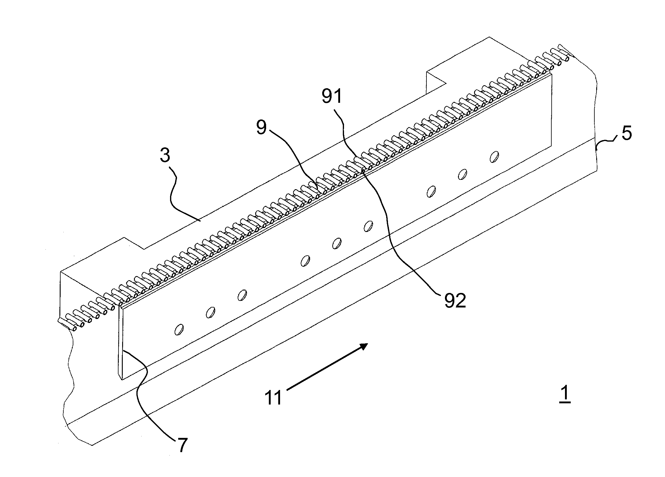
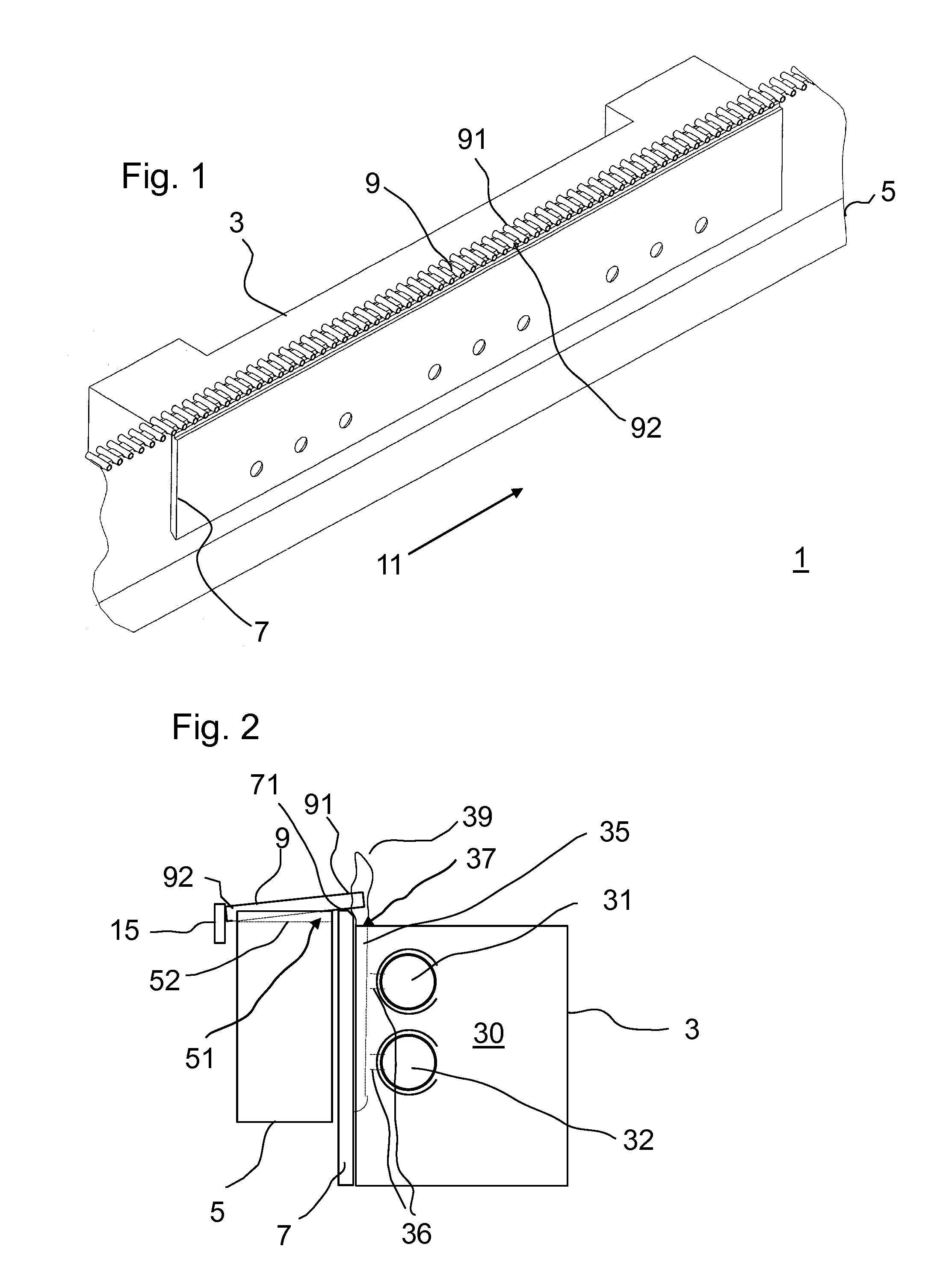
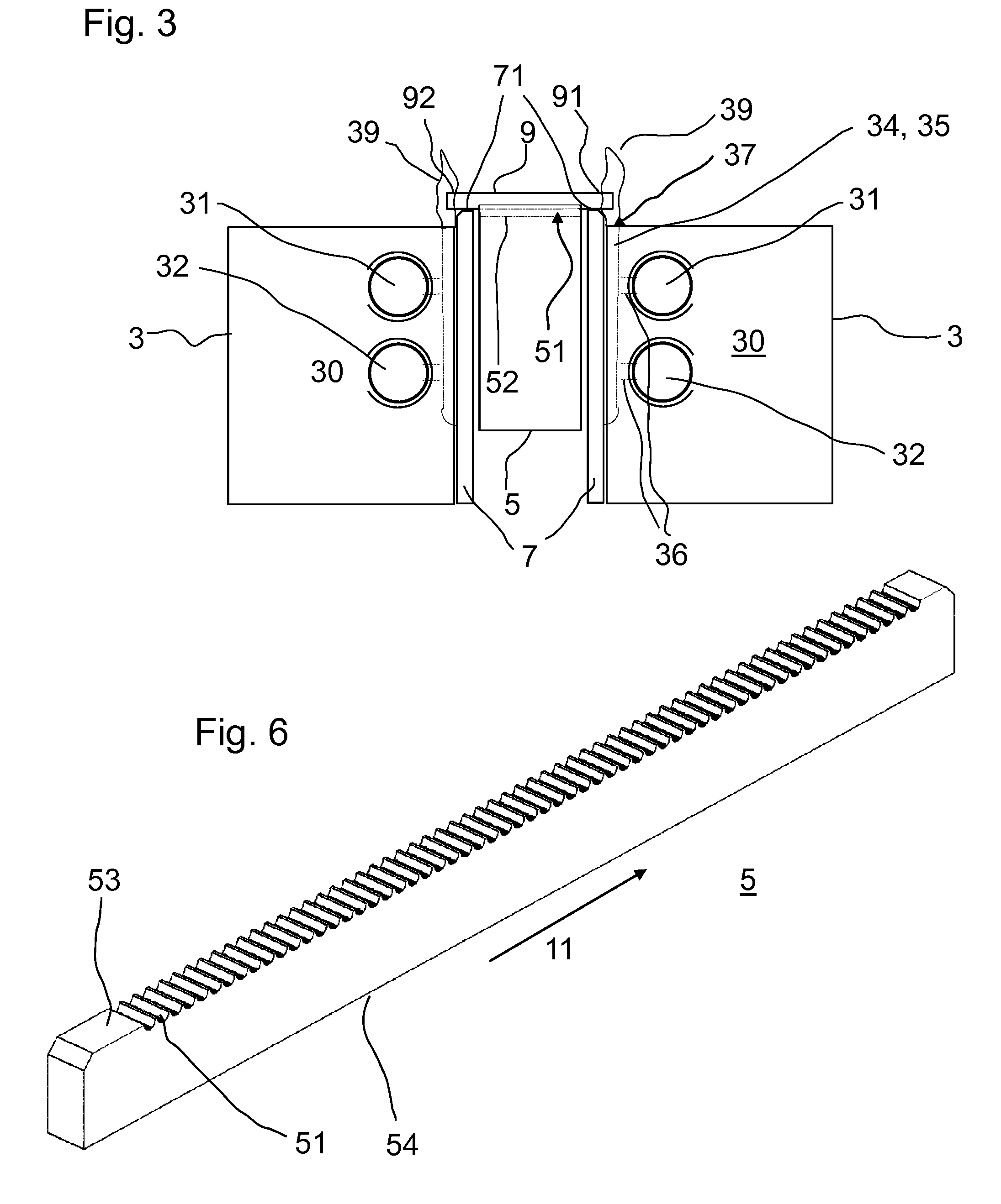
[0039]FIG. 1 shows parts of a device according to the invention which is designated in its entirety by the reference symbol 1. The device 1 for treating the ends 91, 92 of glass rods 9 comprises a burner 3, a carrier 5 with receptacles for placing the glass rods 9 in, an advancing device (not illustrated in FIG. 1) for carrying the carrier 5 past the burner 3 in an advancing direction 11, and a rail 7 which runs along the carrier 5 and whose upper side runs above the lowest point of the receptacles in the region of the burner 3 so that as glass rods 9 which have been inserted into the receptacles are carried past the flames of the burner 5 said glass rods 9 are lifted by the rail 7 by means of the advancing device in the receptacles, and roll on the upper side of the rail 7. In the process, the glass rods 9 are carried past the burner 3 at an advancing speed in the range from 0.1 to 10 cm / s, preferably in the range from 0.5 to 5 cm / s, particularly preferably in the range from 0.8 to...


PUM

PropertyMeasurementUnit
diameteraaaaaaaaaa
speedaaaaaaaaaa
diameteraaaaaaaaaa

Abstract

The invention relates to a method for treating the ends of glass rods in which glass rods are inserted into receptacles in a carrier and with the carrier are carried past a burner and at least one rail in an advancing direction, the flame of the burner melting at least one end of the glass rods and the glass rods being lifted by the rail in the receptacles and rolling on the rail so that the glass rods are made to rotate during the melting process.

Description

FIELD OF INVENTION[0001]The invention relates generally to the post-processing of rod-shaped meltable material, in particular the melting of the ends of glass rods.BACKGROUND OF THE INVENTION[0002]Rod-shaped glass material, either a solid material or in the form of tubes, is subdivided for many applications into sections and these sections re-used. For example, glass tube sections are used to manufacture reed switches. Likewise, glass tube sections are also used as packaging for other electrical and electronic components. Sections of solid glass rods are also used as light guides.[0003]The sections are generally disconnected from the rod by breaking. However, the fractured edges can cause problems. Inter alia, fractures starting from the fractured edges can reduce the stability, have an adverse effect on the visual properties in the case of light guides and lead to leaks in glass tubes. The sharp edges which arise during the breaking process are in many case undesired. In order to a...

Claims


Application Information

Patent Timeline
Patent Type & Authority Applications(United States)
IPC IPC(8): C03B23/04
CPCC03B35/26C03B23/099C03B23/045C03B23/04C03B23/043C03B23/09
Inventor PIEGENDORFER, JOHANNZOTTL, MARTIN
Owner SCHOTT AG
Why Eureka
Try Eureka