Plasma display device

a technology of plasma display panel and display device, which is applied in the direction of gas discharge electrodes, gas discharge vessels/containers, gas discharge tubes, etc., can solve the problems of reactive power consumption and active power consumption of ac-type plasma display panel, and achieve the effect of reducing reactive power and reducing capacitan

Inactive Publication Date: 2010-05-20
SAMSUNG SDI CO LTD
View PDF4 Cites 2 Cited by
  • Summary
  • Abstract
  • Description
  • Claims
  • Application Information

AI Technical Summary

Benefits of technology

[0009]An aspect of an embodiment of the present invention is directed toward a plasma display panel having a decreased reactive power by reducing capacitance between display electrodes that perform surface discharge.

Problems solved by technology

In general, power consumption of an AC-type plasma display panel (PDP) includes active power consumed when discharge is made and reactive power consumed when the discharge is not made.

Method used


Image

  • Plasma display device
  • Plasma display device
  • Plasma display device

Examples


Embodiment Construction

[0060]The present invention will be described more fully hereinafter with reference to the accompanying drawings, in which exemplary embodiments of the invention are shown. As those skilled in the art would realize, the described embodiments may be modified in various different ways, all without departing from the spirit or scope of the present invention. The drawings and description are to be regarded as illustrative in nature and not restrictive. Like reference numerals designate like elements throughout the specification.

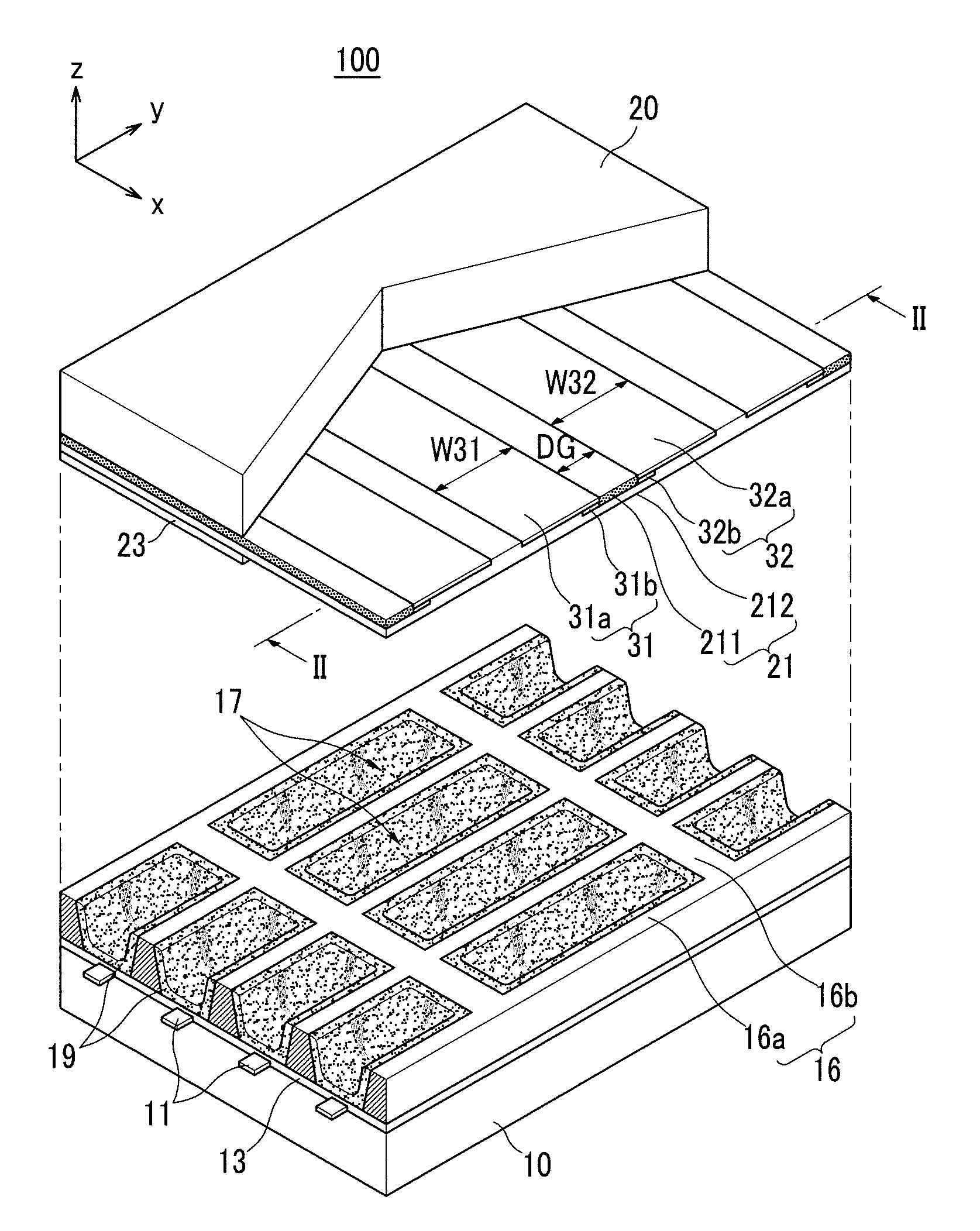
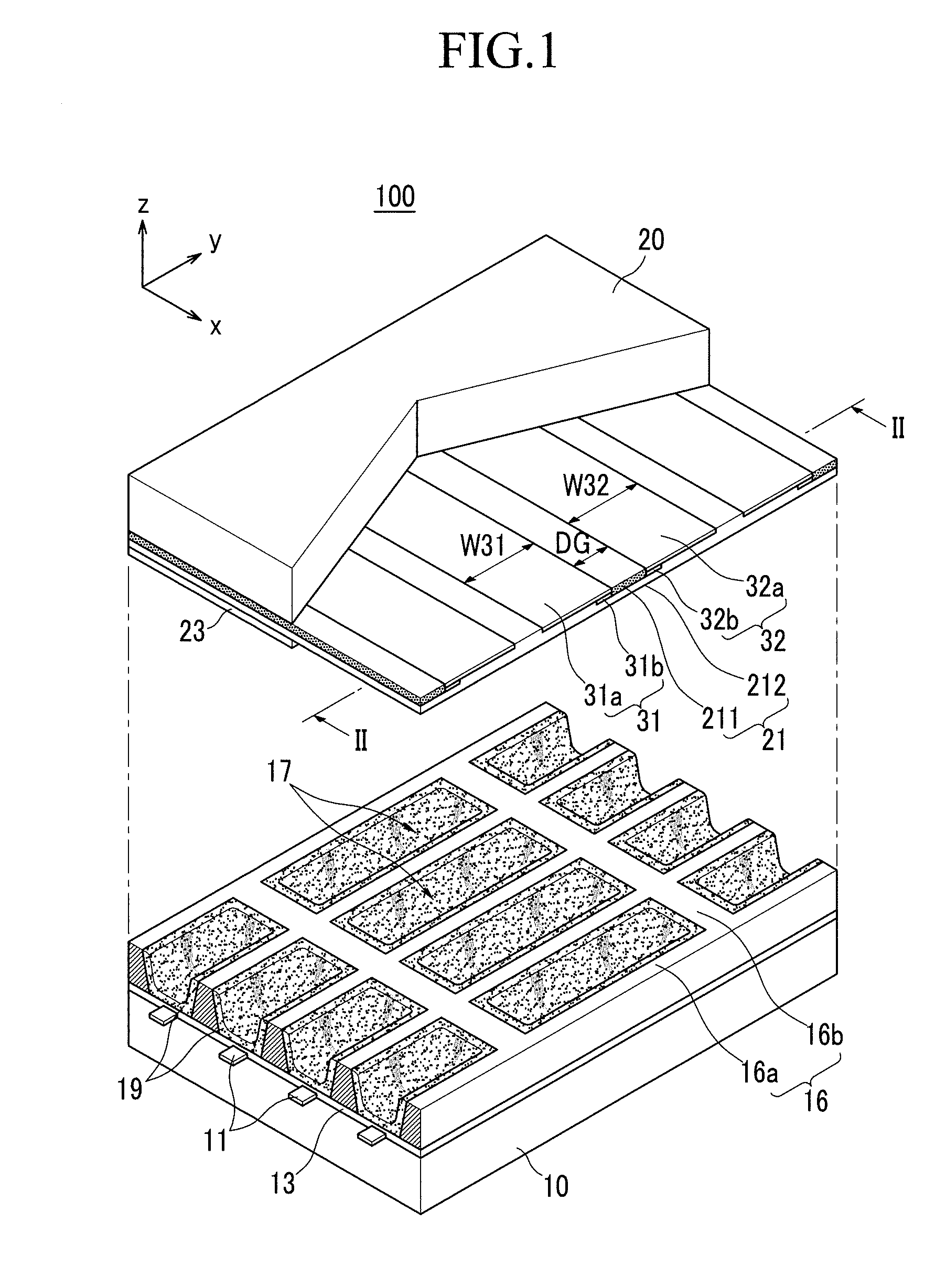
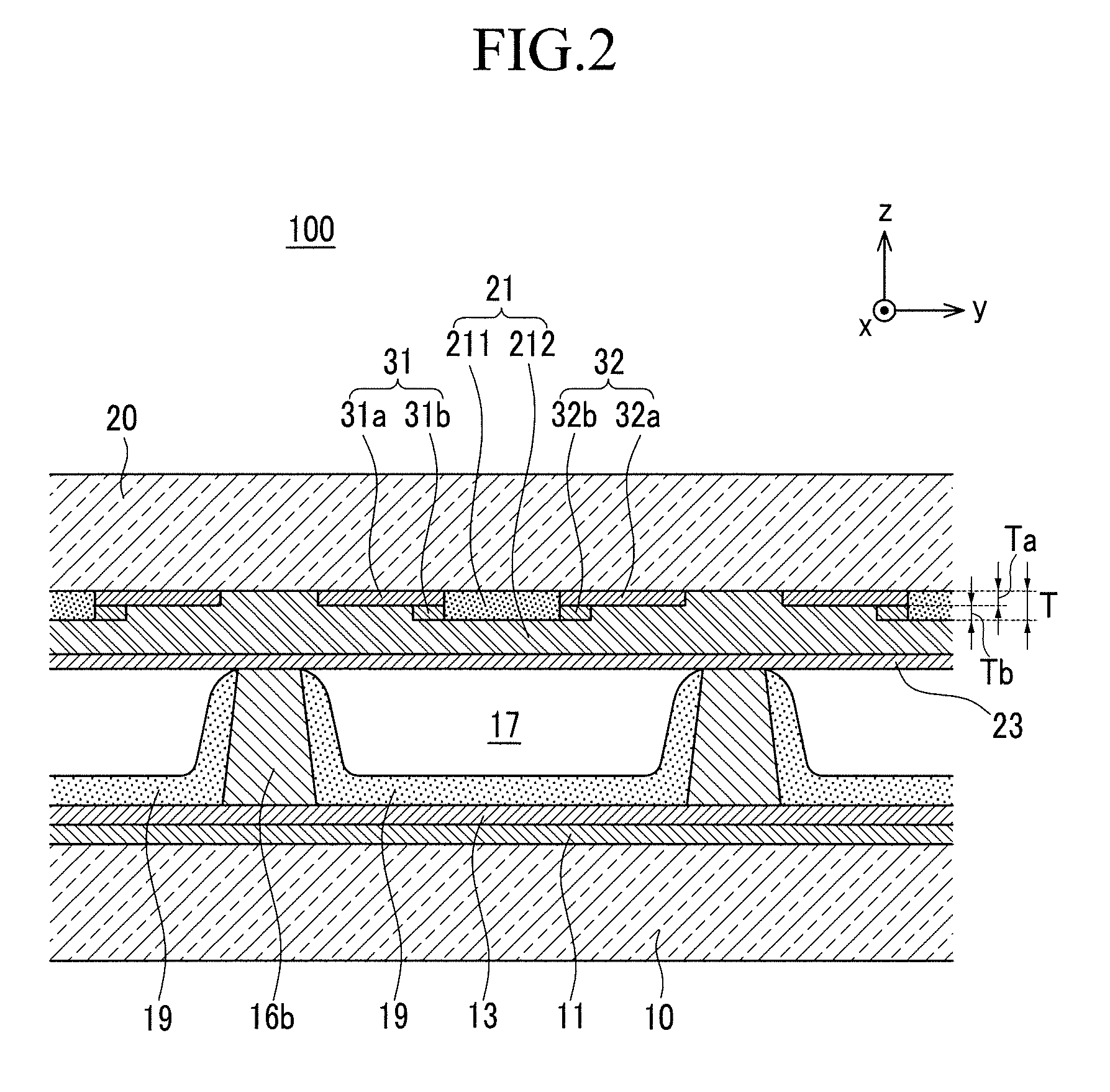
[0061]FIG. 1 is an exploded perspective schematic view of a plasma display panel according to a first exemplary embodiment of the present invention. FIG. 2 is a cross-sectional schematic view taken along line II-II of FIG. 1.

[0062]Referring to FIGS. 1 and 2, the plasma display panel 100 according to the first exemplary embodiment includes a first substrate (hereinafter, “rear substrate”) 10 and a second substrate (hereinafter, “front substrate”) 20 that are attac...


PUM


Abstract

A plasma display panel, including: a first substrate; a second substrate; barrier ribs partitioning a space between the first and second substrates to define discharge cells; address electrodes extending along a first direction to correspond to the discharge cells on a surface of the first substrate and covered with a first dielectric layer; first and second electrodes extending along a second direction crossing the first direction on a surface of the second substrate to define a discharge gap at centers of the discharge cells and covered with a second dielectric layer; and a guide portion that corresponds to at least a part of the discharge gap, wherein the second dielectric layer includes, a first dielectric layer section inside a space defined by the guide portion, and a second dielectric layer section on the first dielectric layer section, and wherein a first dielectric constant is smaller than a second dielectric constant.

Description

CROSS-REFERENCE TO RELATED APPLICATION[0001]This application claims priority to and the benefit of Korean Patent Application No. 10-2008-0115693, filed in the Korean Intellectual Property Office on Nov. 20, 2008, the entire content of which is incorporated herein by reference.BACKGROUND OF THE INVENTION[0002]1. Field of the Invention[0003]The present invention relates to a plasma display panel. More particularly, the present invention relates to a plasma display panel that can reduce reactive power by reducing capacitance between display electrodes that perform surface discharge.[0004]2. Description of the Related Art[0005]In general, power consumption of an AC-type plasma display panel (PDP) includes active power consumed when discharge is made and reactive power consumed when the discharge is not made.[0006]When AC voltage is applied to the PDP, the reactive power is consumed to charge electric charges generated depending on the capacitance. Reactive power consumption is determine...

Claims


Application Information

Patent Timeline
Patent Type & Authority Applications(United States)
IPC IPC(8): H01J17/49
CPCH01J11/12H01J11/38H01J11/24H01J11/32H01J2211/245
Inventor HIROSHI, KANDA
Owner SAMSUNG SDI CO LTD
Why Eureka
Try Eureka