
Duplex document scanning apparatus and method thereof

Active Publication Date: 2010-05-20
GENESYS LOGIC INC
View PDF3 Cites 5 Cited by
  • Summary
  • Abstract
  • Description
  • Claims
  • Application Information

AI Technical Summary

Benefits of technology

[0005]One objective of the present invention is to provide a duplex document scanning apparatus and method thereof for rapidly scanning the document and save the manufacturing cost of the scanning apparatus.

Problems solved by technology

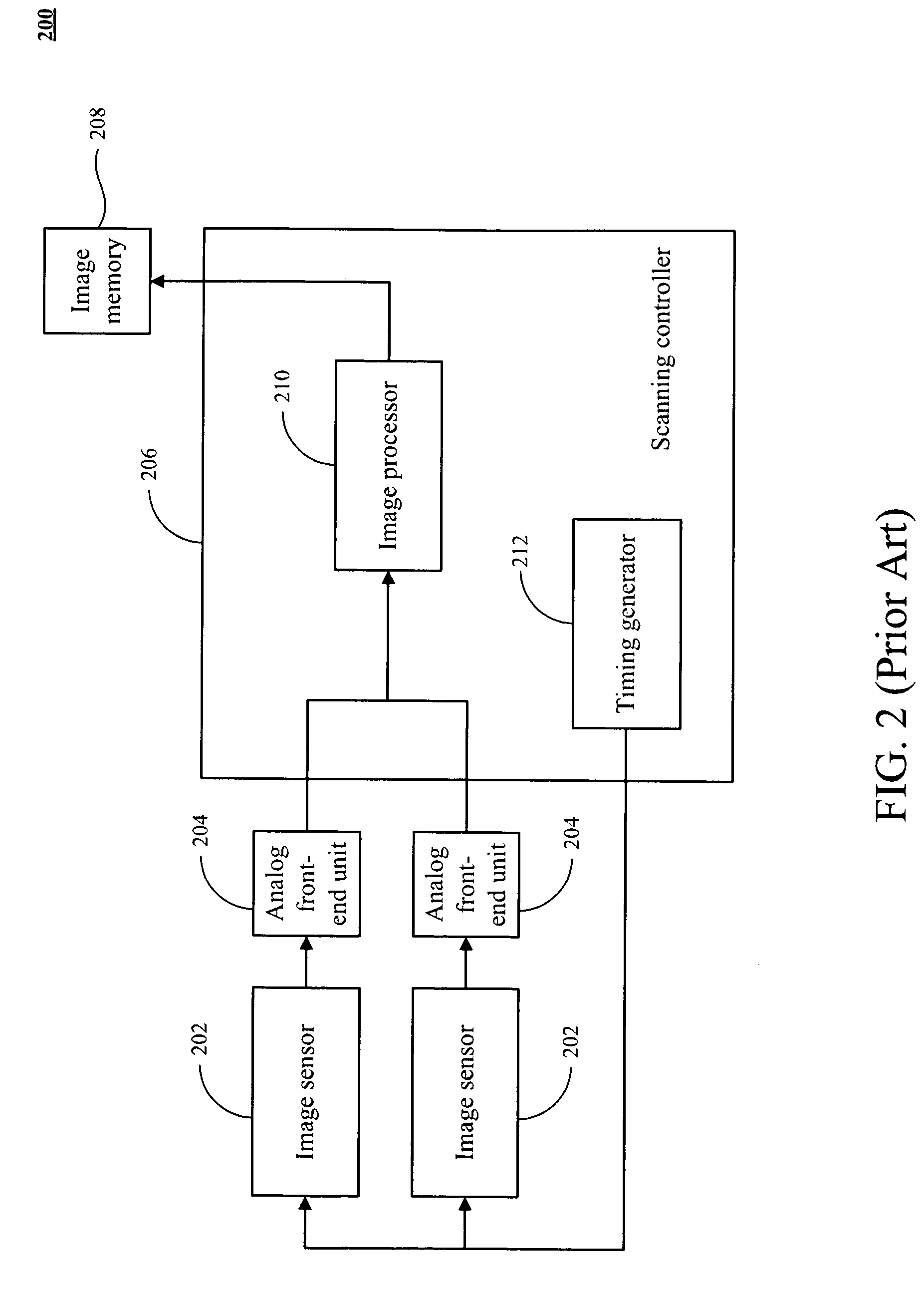
Although the document scanner 200 supports dual-side scanning, however, two analog front-end (AFE) units need to be employed, thereby resulting in no cost-effectiveness.
Moreover, the two analog front-end (AFE) units only output the digital image data sequentially and thus reduces the scanning speed of the document scanner 200.

Method used


Image

  • Duplex document scanning apparatus and method thereof
  • Duplex document scanning apparatus and method thereof
  • Duplex document scanning apparatus and method thereof

Examples


first embodiment

[0028]Please refer to FIG. 3 and FIG. 4. FIG. 4 is a schematic timing waveform of scanning the front-side and back-side of the document 301 at a line-switch-based scanning mode according to the present invention. The timing waveform includes a switch signal (SW), a first timing signal (Sd1) and a combined signal (Sout1+Sout2) of a first analog image signal (Sout1) and a second analog image signal (Sout2). In the timing waveform, the horizontal axis represents time and the vertical axis represents amplitude of the signal. During the line-switch-based scanning mode, the first analog image signal (Sout1) of the first image sensor 302a is composed of a plurality of first scan lines (D1) and the second analog image signal (Sout2) of the second image sensor 302b is composed of a plurality of second scan lines (D2) in the combined signal (Sout1+Sout2). In one embodiment, the data of the first scan lines (D1) and the second scan lines (D2) are represented as high level (e.g. positive voltag...

second embodiment

[0032]Please refer to FIG. 3 and FIG. 5. FIG. 5 is a schematic timing waveform of scanning the front-side and back-side of the document 301 at a pixel-switch-based scanning mode according to the present invention. The timing waveform includes a switch signal (SW), a first analog image signal (Sout1) and a second analog image signal (Sout2). In the timing waveform, the horizontal axis represents time and the vertical axis represents amplitude of the signal. During the pixel-switch-based scanning mode, the first analog image signal (Sout1) of the first image sensor 302a is composed of a plurality of first scan pixels (P1) with period S1 and the second analog image signal (Sout2) of the second image sensor 302b is composed of a plurality of second scan pixels (P2) with period S2. In one embodiment, the data of the first scan pixels (P1) and the second scan pixels (P2) is represented as high level (e.g. positive voltage level). In another embodiment, the data of the first scan pixels (P...


PUM


Abstract

A duplex document scanning apparatus and method thereof are described. The duplex document scanning apparatus includes a first image sensor, a second image sensor, a switch module, a data conversion unit, and a scanning control device. The first image sensor senses the first analog image signal and the second image sensor senses the second analog image signal. The switch module switches the first image sensor and the second image sensor to select the first analog image signal and the second analog image signal. The data conversion unit converts the first and second analog image signals to generate first and second digital image signals. The switch control module of scanning control device generates a switch signal to control the switch module. The scanning control device has a switch control unit and processes the first digital image signal and a second digital image signal. The switch control unit generates a switch signal for controlling the switch module and the switch module simultaneously outputs the first analog image signal and the second analog image signal to the data conversion unit during a signal period of the switch signal.

Description

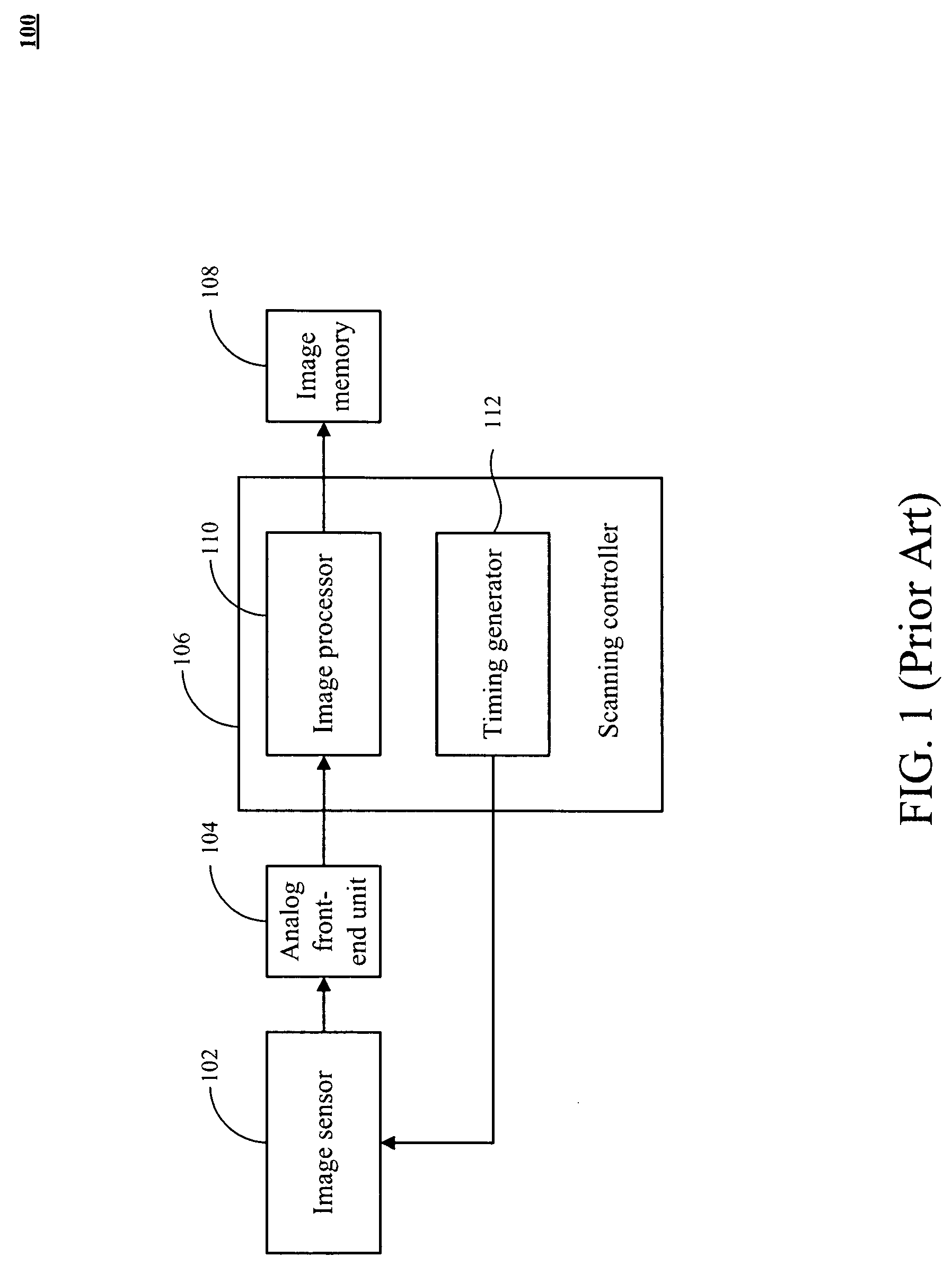
FIELD OF THE INVENTION [0001]The present invention relates to a scanner and method thereof, and more particularly relates to a duplex document scanning apparatus and method thereof.BACKGROUND OF THE INVENTION[0002]With the rapid development of information technology, electrical document are widely used. For the purpose of storage, processing and delivery via internet network of the documents, it is necessary to scan the paper document into the format of electrical documents. However, to rapidly scan the document, there is a need to perform duplex scan (i.e. dual-side scanning) of the document.[0003]FIG. 1 is a schematic block diagram of a conventional document scanner. The document scanner 100 only utilizes one charge coupled device (CCD) or one contact image sensor (CIS), and one analog front-end (AFE) unit. The document scanner 100 includes an image sensor 102, an analog front-end (AFE) unit 104, a scanning controller 106, and image memory 108. The scanning controller 106 further ...

Claims


Application Information

Patent Timeline
IPC IPC(8): H04N1/04
CPCH04N1/193H04N1/2034H04N1/203H04N1/1938
Inventor TSAI, MI-LAI
Owner GENESYS LOGIC INC
Features
  • Generate Ideas
  • Intellectual Property
  • Life Sciences
  • Materials
  • Tech Scout
  • Unparalleled Data Quality
  • Higher Quality Content
  • 60% Fewer Hallucinations
Learn More