Wear-resistant plunger rod

a technology of plunger rods and rods, which is applied in the direction of machines/engines, mechanical equipment, liquid fuel engines, etc., can solve the problems of unit malfunction and poor working condition of the plunger rod, and achieve the effects of reducing the corrosive of the rod, prolonging the operation life of the unit, and improving hardness

Inactive Publication Date: 2010-05-20
ZHEJIANG RONGPENG AIR TOOLS
View PDF9 Cites 0 Cited by
  • Summary
  • Abstract
  • Description
  • Claims
  • Application Information

AI Technical Summary

Benefits of technology

[0005]Said wear-resistant plunger rod is characterized in that: a wear-resistant material (3) whose thickness is in a range of 0.05 to 1.0 mm, is applied on a concavity (4) having same depth and is disposed on a cylindrical surface of said plunger rod (1). Said wear-resistant material (3) can be aluminum oxide ceramic, zirconium oxide ceramic, silicon nitride ceramic or mixture of three. An ultrafine compound powder ceramic can also be added in said wear-resistant material (3) to improve the hardness.
[0006]By applying the material (3) on the surface, the plunger rod (1) is processed through a wear-resistant treatment which can reduce the corrosive of the rod and prolong the operational life of the unit.

Problems solved by technology

Comparison with the rod which only pumps air, the working condition for said plunger rod is relatively poor.
Since variable types of paint contain solvents that may corrode the surface of the rod which has no wear-resistant treatment being processed, the abrasion of the rod occurs eventually and causes the malfunction of the unit.

Method used


Image

  • Wear-resistant plunger rod
  • Wear-resistant plunger rod
  • Wear-resistant plunger rod

Examples


first embodiment

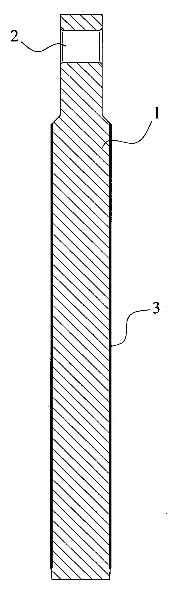
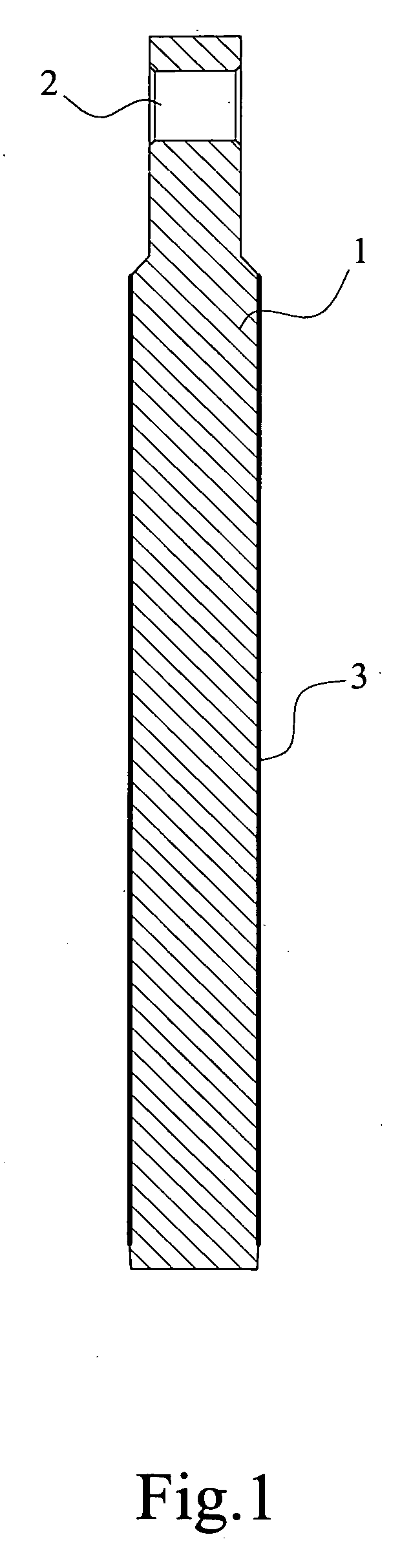
[0012]As shown in. FIG. 1, a wear-resistant plunger rod incorporated in a pump (not shown) of a liquid dispersing means comprises: a rod (1) and a connecting unit (2); said connecting unit (2) is on an end of the rod (1) and is connected to a transmission device (not shown) of a pump of a liquid dispersing means; said rod (1) and connecting unit (2) are integrally formed. Said wear-resistant plunger rod is characterized in that: a wear-resistant material (3) is coating on a surface of said rod (1).

[0013]Applying a coating of wear-resistant material (3) onto the surface of the rod (1) by spraying, the surface is hardened against corrosion and other kinds of wear. Such method is time-saving, cost effective and the thickness of the coating is adjustable.

[0014]Said wear-resistant surface will be processed through a rough finishing and grounded finishing treatment afterward to increase the precision and decrease the unevenness thereof. The hardness and wear resistance is also improving b...

second embodiment

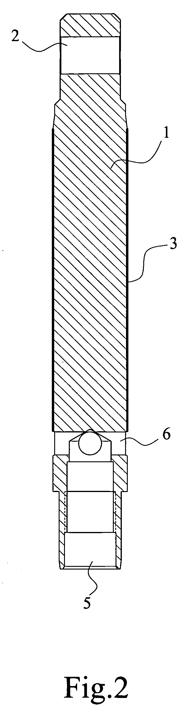
[0016]As illustrated in FIGS. 3 and 4, a second embodiment of the present invention is revealed, a wear-resistant plunger rod as disclosed in second embodiment, incorporated in a pump (not shown) of a liquid dispersing means comprises: a rod (1), a connecting unit (2) and a coating made of wear-resistant material (3). Said rod (1) and connecting unit (2) are integrally formed, which means both rod (1) and connecting unit (2) are manufacture from a rod-like material and processed by machine. Said connecting unit (2) is on an end of the rod (1) and is connected to a transmission device (not shown) of a pump of a liquid dispersing means; Said coating of wear-resistant material (3) is applied on a concavity (4), disposed on a cylindrical surface of said rod (1), whose depth corresponds the required thickness of said wear-resistant material (3).

[0017]The plunger rod of the second embodiment has the same main structure as disclosed in the first embodiment, with difference by having a conn...


PUM

PropertyMeasurementUnit
thicknessaaaaaaaaaa
thicknessaaaaaaaaaa
hardnessaaaaaaaaaa

Abstract

A wear-resistant plunger rod incorporated in a pump of a paint spraying units comprises: a rod (1) and a connecting unit (2) integrally formed. Said connecting unit (2) is disposed on another end of the rod (1) and connected to a transmission device of a pump of a liquid dispersing means. Said wear-resistant plunger rod is characterized in that: a wear-resistant material (3) is applied on the surface of said plunger rod (1). By applying the material (3) on the surface, the plunger rod (1) is given property of wear resistant which increases the liability and safety and prolongs the operational life of the unit.

Description

FIELD OF THE INVENTION[0001]The present invention relates to a wear-resistant plunger rod incorporated in a pump of a paint spraying unit.BACKGROUND OF THE INVENTION[0002]A plunger rod is an essential element of a pump which incorporated in a paint dispersing unit, its reciprocal movements pumps the air out to mix the paint, forming pluralities of tiny paint drops, thus, user can spray it evenly on a surface of an object. A plunger rod of a conventional air spray unit usually contacts with air only. However, in an electric or airless paint spraying units a plunger rod may contacts with the paint directly. Comparison with the rod which only pumps air, the working condition for said plunger rod is relatively poor. Since variable types of paint contain solvents that may corrode the surface of the rod which has no wear-resistant treatment being processed, the abrasion of the rod occurs eventually and causes the malfunction of the unit.SUMMARY OF THE INVENTION[0003]To solve aforementione...

Claims


Application Information

Patent Timeline
Patent Type & Authority Applications(United States)
IPC IPC(8): F16J1/00
CPCF05C2253/12F04B53/144
Inventor LI, XIAO-PENG
Owner ZHEJIANG RONGPENG AIR TOOLS
Why Eureka
Try Eureka