Managing gas bubbles in a liquid flow system

Inactive Publication Date: 2010-05-20
MTI MICROFUEL CELLS
View PDF4 Cites 10 Cited by
  • Summary
  • Abstract
  • Description
  • Claims
  • Application Information

AI Technical Summary

Benefits of technology

[0013]Advantageously, the novel system manages bubbles in a liquid flow system. In particular, by substantially preventing formation of intolerably sized bubbles and aggregation of tolerably sized bubbles into intolerably sized bubbles, the novel technique provides solutions to various problems associated with bubbles in liquid flow systems. For example, finely divided and distributed bubbles in the liquid reactant

Problems solved by technology

For instance, bubbles may form that are intolerably large in size, and may cause problems for the liquid receiving device, whose degree of severity varies with the particular type of liquid receiving device and the occurrence of bubbles within the liquid flow to that device.
This leads to dropouts in the fuel cell power generation, such dropouts being proportional in their severity to the size of the bubbles, and the amount of time that passes before the fuel line begins to again deliver liquid reactant (e.g., methanol fuel) to the electrochemical energy conversion device (e.g., fuel cell).
Larger bubbles are particularly burdensome for the flow system 100.
In addition, many other liquid receiving devices are also sensitive to bubbles in the liquid flow, such as various medical devices, paint supply systems, power plants, etc.
Air bubbles flowing within a medical device may have particularly severe consequences, such as fatality of a patient or other less sever outcomes, as may be appreciated by those skilled in the art.
Also, paint supply systems may suffer from bubbles, such as where finely detailed paint projects (

Method used


Image

  • Managing gas bubbles in a liquid flow system
  • Managing gas bubbles in a liquid flow system
  • Managing gas bubbles in a liquid flow system

Examples


Embodiment Construction

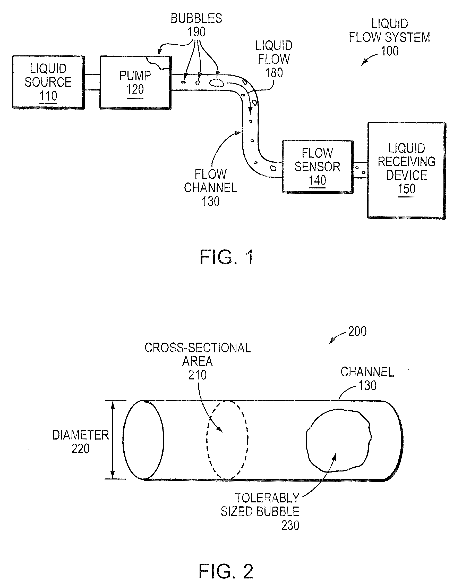
[0026]FIG. 1 is a simplified schematic illustration of one embodiment of a liquid flow system 100 that may be advantageously used with the present invention. The system 100 comprises a liquid source 110 interconnected to a liquid receiving device 150 via flow channel / conduit 130 through which liquid 180 may flow. To move the liquid, a pump 120 (e.g., electrical, mechanical, etc.) may be placed along the flow channel 130. Also, one or more flow sensors 140 may be placed along the flow channel 130 to monitor various conditions of the flow, such as rate, volume, temperature, pressure, etc.

[0027]Illustratively, the liquid receiving device 150 is an electrochemical energy conversion device or fuel cell system, e.g., a direct oxidation fuel cell, direct methanol fuel cell (DMFC), liquid or vapor feed fuel cell (fed by liquid in flow channel 130), portable fuel cell, transportable reformer-based fuel cell system, or other devices powered by a liquid fuel or other reactant, as will be under...


PUM

PropertyMeasurementUnit
Grain sizeaaaaaaaaaa
Volumeaaaaaaaaaa

Abstract

A system and method for managing gas bubbles in a liquid flow system are described. In particular, according to the system and method, novel techniques reduce a volume of cavities in the liquid flow system and limit a cross-sectional area of the liquid flow system to a maximum cross-sectional area of tolerably sized bubbles. In this manner, by reducing the cavity volumes and limiting cross-sectional areas, the formation of intolerably sized bubbles and the aggregation of tolerably sized bubbles into intolerably sized bubbles are each substantially prevented. Also, bubbles may be removed from the system to reduce the quantity of bubbles that are to be managed.

Description

BACKGROUND OF THE INVENTION[0001]1. Field of the Invention[0002]This invention relates generally to liquid flow systems, and, more particularly, to managing bubble sizes in liquid flow systems.[0003]2. Background Information[0004]There are many types of devices that are configured to receive liquid that are sensitive to bubbles within the liquid. For instance, bubbles may form that are intolerably large in size, and may cause problems for the liquid receiving device, whose degree of severity varies with the particular type of liquid receiving device and the occurrence of bubbles within the liquid flow to that device.[0005]One example device sensitive to bubbles in liquid flow are electrochemical energy conversion devices, such as fuel cells. Many fuel cell systems utilize pumps to move fluids / liquids within the system, e.g., from a reactant / fuel source to the fuel cell. Various types of pumps are well known to those skilled in the art. Often, these pumps may generate gases, which, u...

Claims


Application Information

Patent Timeline
IPC IPC(8): B01D19/00H01M8/04
CPCB01D19/0042B01D19/0047B01D19/0063Y02E60/50H01M8/04089H01M8/04201B01D19/0068
Inventor MESCHTER, JOHN E.PRUEITT, JAMES K.BISHOP, PAULMILLER, ROBERTTHATCHER, KARENGRYGUS, BRYANCHEN, MICHAELQI, ZHIGANG
Owner MTI MICROFUEL CELLS
Why Eureka
Try Eureka