Storage control apparatus and storage system

a storage control and control apparatus technology, applied in the direction of memory adressing/allocation/relocation, instruments, computing, etc., can solve the problems of low reliability, low efficiency, and low efficiency of nonvolatile memory, so as to improve the efficiency of use and improve the reliability. , the effect of high reliability

Inactive Publication Date: 2010-05-20
HITACHI LTD
View PDF6 Cites 7 Cited by
  • Summary
  • Abstract
  • Description
  • Claims
  • Application Information

AI Technical Summary

Benefits of technology

[0017]According to the aspects of the invention, the use efficiency can be increased for memories for use with input / output control of a storage control apparatus and a storage system. Moreover, in the storage control apparatus, input / output control over staging and destaging between the cache memory and the storage device can be performed with high reliability and swiftness.

Problems solved by technology

A volatile memory is generally slow in input / output speed of data, and any data stored therein is erased when the power supply is turned off.
On the other hand, a nonvolatile memory is high in performance, i.e., generally fast in input / output speed of data, and any data stored therein remains intact even if the power supply is turned off, but is relatively high in cost.
On the other hand, the dirty data is the one being updated and existing only on the cache memory, for example, and is not able to be recovered if it is erased.
The control data is the one that will cause trouble in terms of controlling if it is erased, and the storage data is the one merely stored by a user.

Method used


Image

  • Storage control apparatus and storage system
  • Storage control apparatus and storage system
  • Storage control apparatus and storage system

Examples


first embodiment

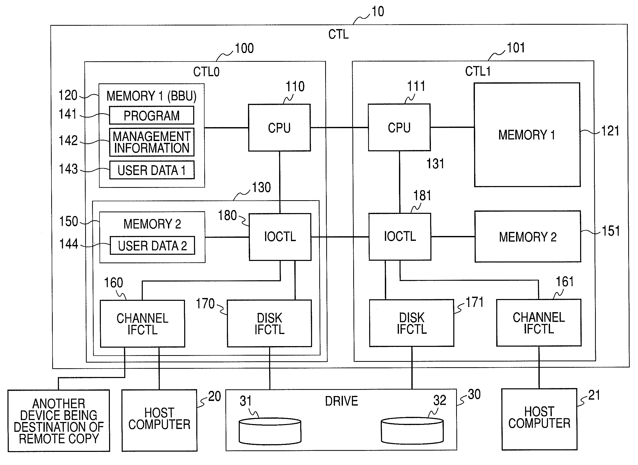
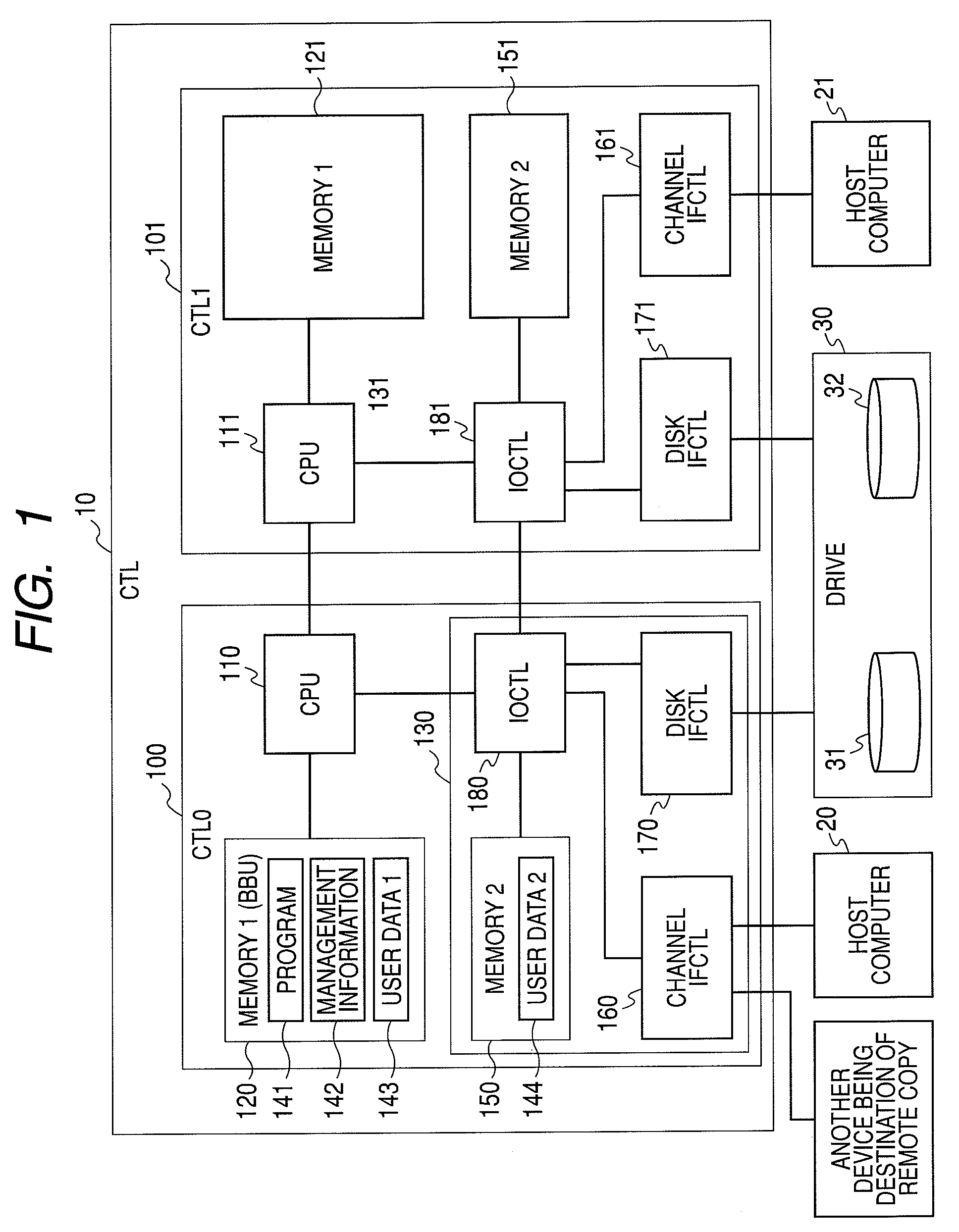
[0031]FIG. 1 is a schematic overall view of a storage system provided therein with a storage control apparatus in the first embodiment of the invention. FIG. 2 shows an exemplary storage area management table showing the configuration of a memory space in the storage control apparatus of the invention.

[0032]In FIG. 1, a reference numeral 10 denotes a storage control system, reference numerals 20 and 21 each denote a host computer, a reference numeral 30 denotes a storage device (drive), reference numerals 31 and 32 each denote a disk drive, reference numerals 100 and 101 each denote a storage control apparatus, reference numerals 110 and 111 each denote a Central Processing Unit (CPU), reference numerals 120 and 121 each denote a main memory device (memory 1), reference numerals 130 and 131 each denote an input / output control module (IO module), a reference numeral 141 denotes a program, a reference numeral 142 denotes management information, a reference numeral 143 denotes user dat...

second embodiment

[0041]FIG. 3 shows a schematic overall view of a storage system provided therein with a storage control apparatus in a second embodiment of the invention. In FIG. 3, the reference numeral 10 denotes a storage control system, the reference numerals 20 and 21 each denote a host computer, the reference numeral 30 denotes a storage device (drive), the reference numerals 31 and 32 each denote a disk drive, the reference numerals 100 and 101 each denote a storage control apparatus, the reference numerals 110 and 111 each denote a Central Processing Unit (CPU), the reference numerals 120 and 121 each denote a main memory device (memory 1), the reference numerals 130 and 131 each denote an input / output control module (IO module), the reference numeral 141 denotes a program, the reference numeral 142 denotes management information, the reference numeral 143 denotes user data 1, the reference numeral 144 denotes user data 2, the reference numerals 150 and 151 each denote a cache memory (memor...

third embodiment

[0047]FIG. 4 is a schematic overall view of a storage system including a storage control apparatus in a third embodiment of the invention. In FIG. 4, the reference numeral 10 denotes a storage control system, the reference numerals 20 and 21 each denote a host computer, the reference numeral 30 denotes a storage device (drive), the reference numerals 31 and 32 each denote a disk drive, the reference numerals 100 and 101 each denote a storage control apparatus, the reference numerals 110 and 111 each denote a Central Processing Unit (CPU), the reference numerals 120 and 121 each denote a main memory device (memory) 1, the reference numerals 130 and 131 each denote an input / output control module (IO module), the reference numeral 141 denotes a program, the reference numeral 142 denotes management information, the reference numeral 143 denotes user data 1, the reference numeral 144 denotes user data 2, the reference numerals 150 and 151 each denote a cache memory (memory 2), the refere...


PUM


Abstract

Provided is a storage control apparatus, including a Central Processing Unit, a channel interface device, a disk interface device, and an input/output control device. In the storage control apparatus, a main memory device is configured by a battery-backed-up volatile memory that can maintain the nonvolatility of data for a predetermined period of time after the power supply is turned off. By the battery-backed-up main memory device and a memory device of the input/output control device, a memory address space is formed to make it serve as a cache device of the storage control apparatus, and staging and destaging processes are executed between the cache device and the disk drive unit. In such a storage control apparatus being coupled to a host computer and a storage device to control data input/output to/from the storage device, memory devices therein can be used with a good efficiency, and data input/output control can be performed with high reliability and swiftness.

Description

CROSS REFERENCES TO RELATED APPLICATIONS[0001]This application relates to and claims priority from Japanese Patent Application No. 2008-293330, filed on Nov. 17, 2008, the entire disclosure of which is incorporated herein by reference.BACKGROUND OF THE INVENTION[0002]1. Field of the Invention[0003]The present invention relates to a storage control apparatus and a storage system with which the use efficiency of a memory is increased in a control device in charge of data input / output to / from a storage device.[0004]2. Description of the Related Art[0005]There is a technology of making use of a plurality of memories, e.g., disk memories and cache memories, for control over data input / output to / from a storage device provided therein with a plurality of disk drives. As such a technology, Patent Document 1 (JP-A-59-135563) describes, for example, a computer system in which a disk / cache device to be coupled to a disk control device is configured by a portion of nonvolatile memory and a port...

Claims


Application Information

Patent Timeline
Patent Type & Authority Applications(United States)
IPC IPC(8): G06F12/08G06F12/00
CPCG06F12/0804G06F2212/2228G06F12/0868
Inventor KANAI, HIROKI
Owner HITACHI LTD
Why Eureka
Try Eureka