
Electromechanical brake booster

a brake booster and electromechanical technology, applied in the direction of braking systems, rotary clutches, fluid couplings, etc., can solve the problems of inability to provide an adequate underpressure and unwanted connection of an underpressure brake booster, and achieve the effect of reducing the force required for releasing the master cylinder

Inactive Publication Date: 2010-05-27
ROBERT BOSCH GMBH
View PDF3 Cites 47 Cited by
  • Summary
  • Abstract
  • Description
  • Claims
  • Application Information

AI Technical Summary

Benefits of technology

[0016]The advantage of this feature of the invention is that an actuation of the master cylinder is possible if the brake booster fails, and only a few, or in any case not all, of the parts of the brake booster have to be jointly moved. There is low motion resistance of the non-moved brake booster to an actuation of the master cylinder. A further advantage of the invention is a comparatively simple, economical design and the possibility of using a conventional electric motor. In comparison with a hollow rotor motor, the lower moment of mass inertia is another advantage. In an accident, a retraction, that is, a motion of the brake pedal in the direction of a brake actuation, is possible with the brake booster of the invention, for reducing the risk of injury.
[0017]Claim 14 contemplates a shiftable free wheel mechanism, which in the engaged state acts a free wheel mechanism and in the disengaged state disconnects the electric motor of the brake booster, and preferably also its gear or parts of the gear, mechanically from the master cylinder. By disengaging the free wheel mechanism, a release of the master cylinder without a motion of the brake booster is possible; at the least, not all the parts of the brake booster have to be jointly moved. The force required for releasing the master cylinder is reduced as a result.
[0018]Further characteristics of the invention will become apparent from the ensuing

Problems solved by technology

In modern internal combustion engines, the problem sometimes occurs that they fail to furnish an adequate underpressure for an underpressure brake booster, or that connecting an underpressure brake booster is unwanted because of its influence on the intake performance, or in other words on the delivery of the combustion air.

Method used


Image

  • Electromechanical brake booster
  • Electromechanical brake booster
  • Electromechanical brake booster

Examples


Embodiment Construction

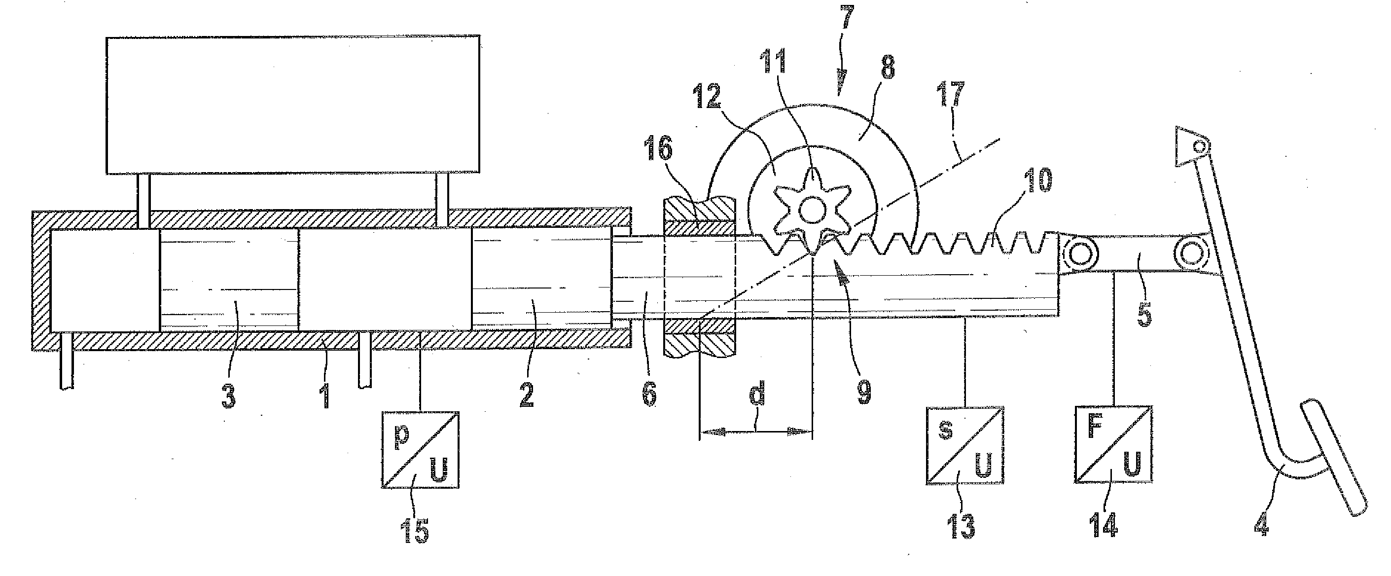
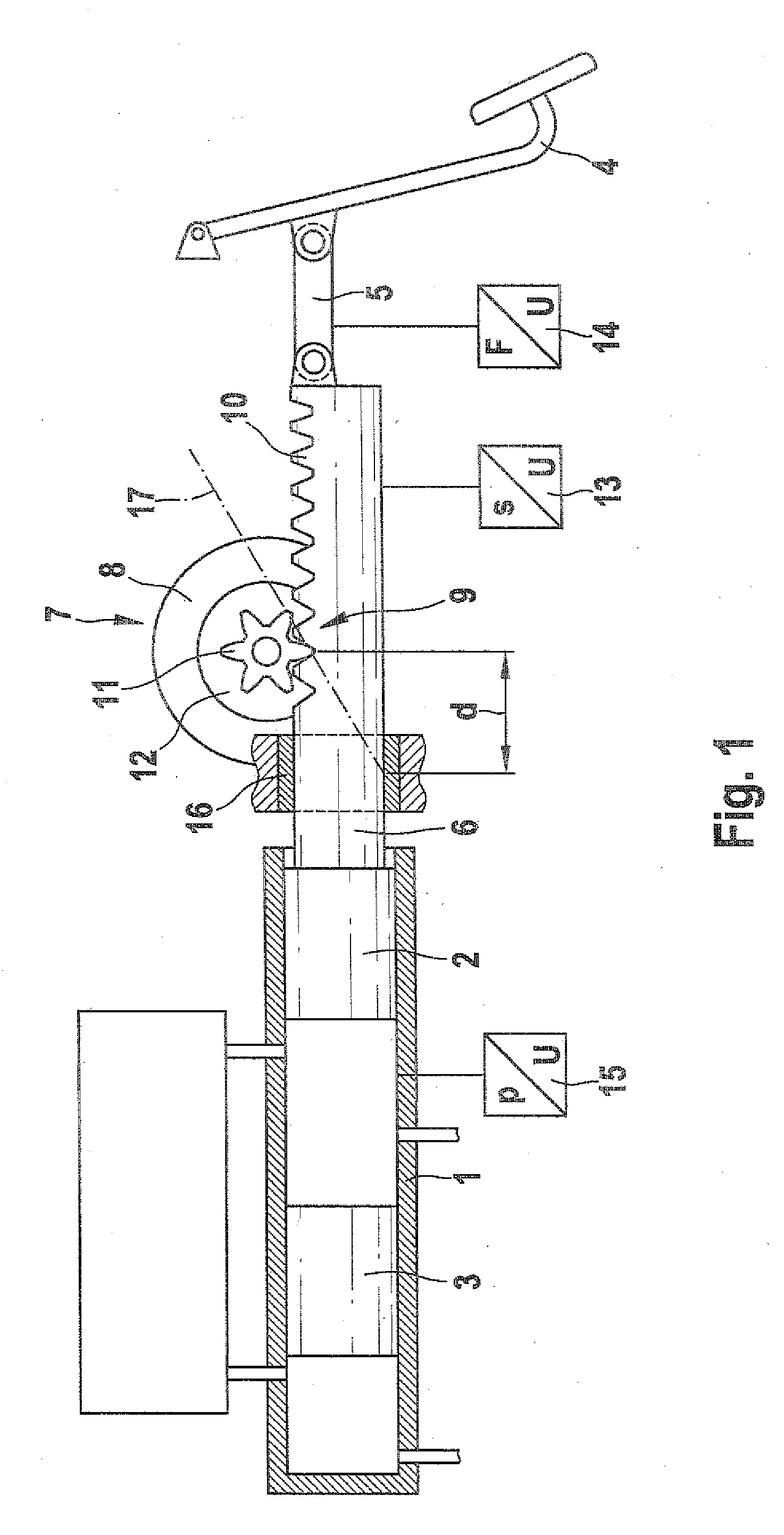
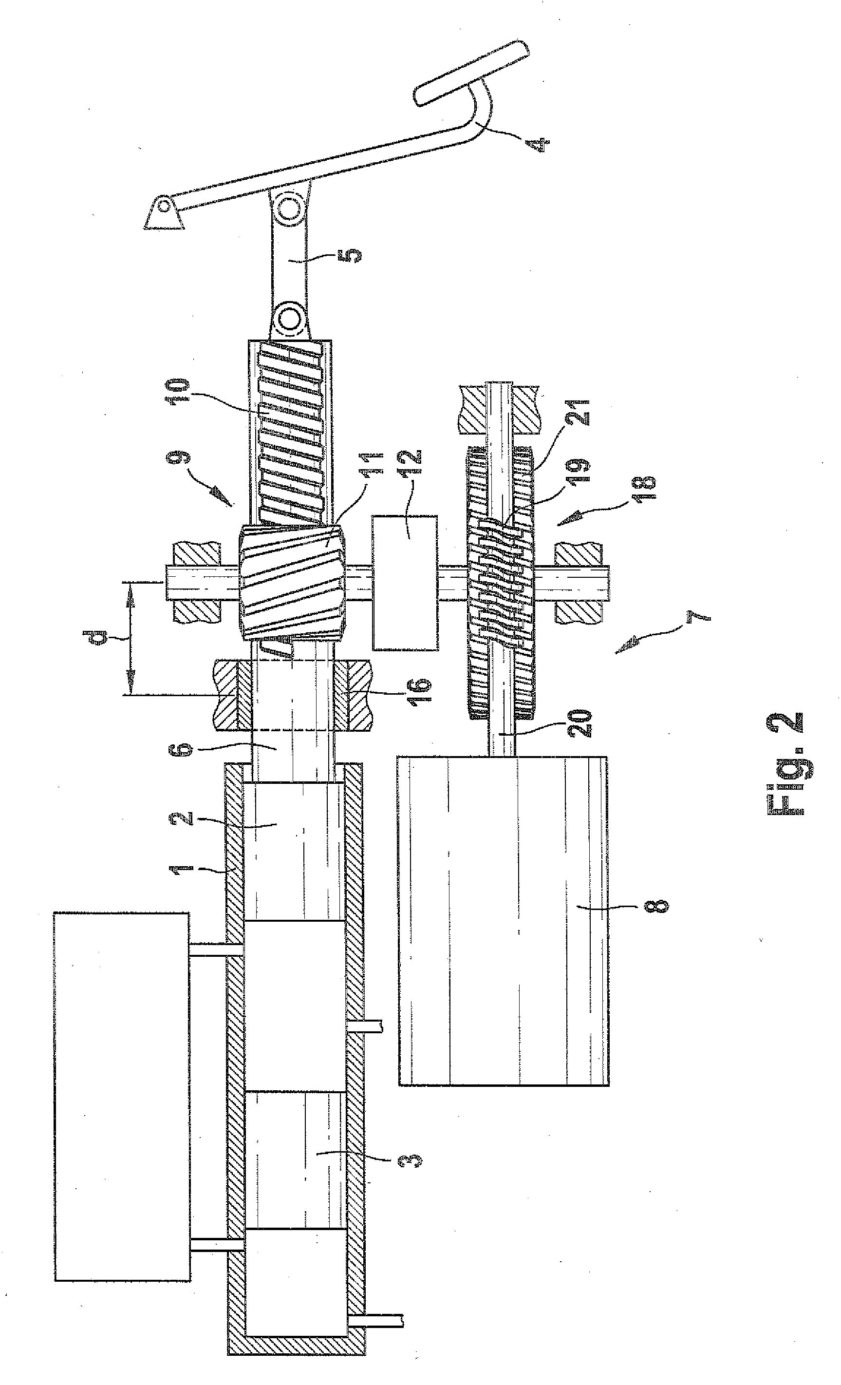
[0020]FIG. 1 schematically shows a master cylinder 1 of a hydraulic vehicle brake system, not otherwise shown, of a motor vehicle. A rod piston 2 and a floating piston 3 are received in the master cylinder 1. The rod piston 2 is moved mechanically with a brake pedal 4, via a tappet rod 5 and a piston rod 6. The tappet rod 5 connects the piston rod 6 in articulated fashion to the brake pedal 4. The floating piston 3 is subjected to and moved by a hydraulic pressure that the rod piston 2 generates upon its displacement into the master cylinder 1. If there is a leak, the floating piston 3 is moved by contact with the rod piston 2. This is known per se and requires no further explanation. The piston rod 6 is rigidly connected to the rod piston 2, and the piston rod 6 may be in one piece with the rod piston 2.

[0021]An electromechanical brake booster 7 in accordance with the invention is disposed between the brake pedal 4 and the master cylinder 1. The brake booster 7 has an electric moto...


PUM


Abstract

The invention relates to an electromechanical brake booster for a master brake cylinder of a hydraulic vehicle braking system. The invention provides to configure the brake booster such that it preferably includes a switchable freewheel, which enables an actuation of the master brake cylinder without any movement of the electric motor of the brake booster. The invention further provides to configure the brake booster such that it includes a mechanical gear having a variable transmission ratio, which has a high path transmission at the beginning of an actuation of the master brake cylinder, and a force transmission that rises with increasing actuation. A variable gear ratio is possible using a rack and pinion gear, the toothed rack of which has a soothing with a pitch that changes across the length of the toothed rack. A further possibility of a mechanical gear having a variable ratio is a toggle lever mechanism.

Description

PRIOR ART[0001]The invention relates to an electromechanical brake booster having the characteristics of the preamble to claim 1.[0002]In motor vehicles at this time, underpressure brake boosters are usual, which utilize an underpressure in an intake tube of an internal combustion engine of the motor vehicle to generate an auxiliary force that boosts a muscle power exerted by a vehicle driver for actuating a brake system of the motor vehicle. The underpressure brake boosters are typically flanged to a master cylinder; that is, they are disposed between a brake pedal and the master cylinder, and they introduce their auxiliary force between the brake pedal and a piston of the master cylinder. When the term brake pedal is used hereinafter, it is to be understood also to encompass a hand brake lever or other actuating element for a hydraulic vehicle brake system.[0003]In modern internal combustion engines, the problem sometimes occurs that they fail to furnish an adequate underpressure ...

Claims


Application Information

Patent Timeline
IPC IPC(8): F15B7/00B60T13/74
CPCB60T13/745B60T7/042
Inventor NAGEL, WILLIHOFMANN, DIRK
Owner ROBERT BOSCH GMBH
Learn More