Cmc mixer with structural outer cowling

a mixer and outer cowling technology, applied in the field of nozzles, can solve the problems of increasing the weight of the nozzle, increasing the mechanical load on the flange of the exhaust casing of the nozzle, and still presenting certain drawbacks, so as to reduce the number of metallic parts, reduce the stress applied, and increase the weight

Active Publication Date: 2010-05-27
SAFRAN CERAMICS SA
View PDF6 Cites 35 Cited by
  • Summary
  • Abstract
  • Description
  • Claims
  • Application Information

AI Technical Summary

Benefits of technology

[0015]An object of the present invention is to propose a novel design of mixer having a structure with CMC lobes, in which the number of metallic parts can be reduced so as to further increase savings in weight, while reducing the stresses applied to the lobed structure, in order to improve its lifetime.

Problems solved by technology

Nevertheless, although a mixer of that type does indeed improve the efficiency and the noise performance of a turbojet having a separate-stream nozzle, it inevitably leads to an increase in the weight of the nozzle, with that having an impact on the overall dynamics of the engine and on its connection with the pylon of the airplane.
Such a mixer presents non-negligible additional weight that is cantilevered out in the engine, thereby leading to an increase in the mechanical loading on the flange of the exhaust casing of the nozzle.
The operation of that mixer has been proven, but although its architecture enables a significant weight saving to be achieved (about 40%) compared with a one-piece metallic mixer, it nevertheless still presents certain drawbacks.
Incorporating the lobed structure 41 made of CMC material requires a large number of metallic parts to be used, thereby encroaching on the weight savings.
Furthermore, those flexible connections, and in particular the tabs 43, need to accommodate steep temperature gradients leading to high levels of mechanical stress in the lobed structure, thereby reducing its lifetime.
Finally, the presence of the stiffener ring gives rise to losses of performance, leading to an increase in the specific consumption of the turbojet, thereby limiting to some extent the benefit obtained by lightning the weight of the mixer.

Method used


Image

  • Cmc mixer with structural outer cowling
  • Cmc mixer with structural outer cowling
  • Cmc mixer with structural outer cowling

Examples


Embodiment Construction

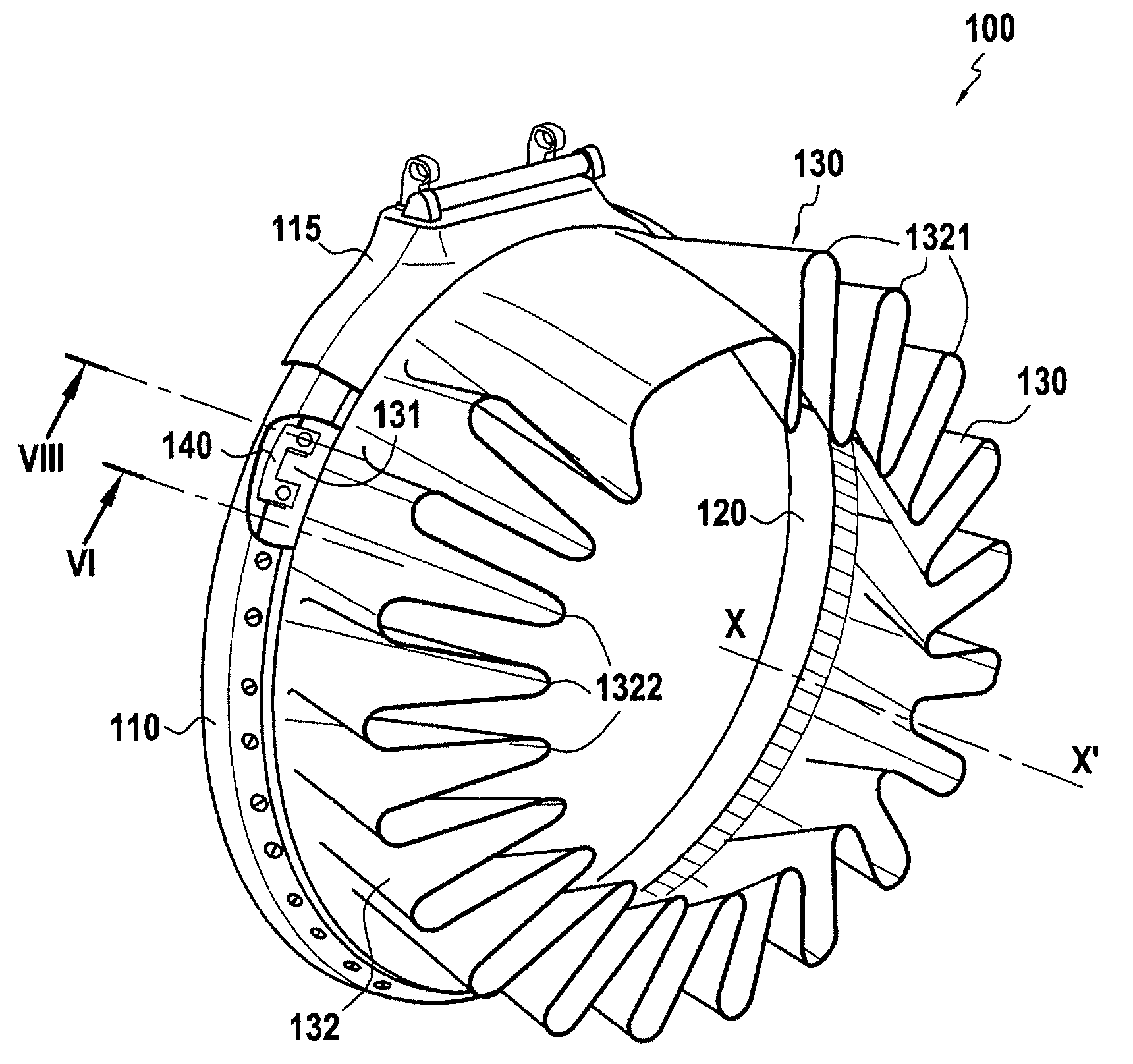
[0039]FIG. 4 shows a mixer 100 for a separate-stream turbojet nozzle constituting an embodiment of the invention. The mixer, which extends along a longitudinal axis X-X′, comprises an inner shroud 120 of metallic material (e.g. Inconel® 625) defining a flow channel for the hot inner stream, an outer shroud 110 of metallic material (e.g. Inconel® 625) for connecting the mixer to the exhaust casing of a turbojet nozzle (not shown), and a lobed structure 130 at the downstream end of which mixing takes place between the hot inner stream from the turbojet combustion chamber (also referred to as the primary stream) that flows inside the mixer, and the cold outer stream, e.g. coming from the upstream fan (also referred to as the secondary stream) that flows outside the mixer.

[0040]The lobed structure 130 presents an upstream portion 131 for attaching to the outer shroud 110 of the mixer. In order to improve the performance of the turbojet, the structure 130 comprises a downstream portion 1...


PUM

PropertyMeasurementUnit
diameteraaaaaaaaaa
flexibleaaaaaaaaaa
cylindrical shapeaaaaaaaaaa

Abstract

The invention relates to a mixer (100) for a separate-stream nozzle of a turbojet, the mixer being designed to mix a hot inner stream from the combustion chamber of the turbojet with a cold outer stream from the fan of the turbojet. The mixer comprises an inner shroud (120) defining a flow channel for said hot inner stream, an outer shroud (110) disposed around the inner shroud (120) and co-operating therewith to define a flow channel for said cold outer stream, and a lobed structure (130) having lobes (1321, 1322) extending longitudinally from the trailing edges (110a, 120a) of said shrouds. The lobed structure (130) is made of a ceramic matrix composite material and is attached to the outer shroud (110) by flexible fastener tabs (140).

Description

BACKGROUND OF THE INVENTION[0001]The present invention relates to the general field of nozzles that are fitted to airplane turbojets. The invention relates more particularly to the separate-stream nozzles fitted with stream mixers that served to improve the performance of the engine while also reducing the noise emitted by the jet leaving the outlet from the nozzle.[0002]More precisely, as shown very diagrammatically in FIG. 1, a separate-stream nozzle for a turbojet typically comprises, from the inside towards the outside, a central body 12 (also referred to as a “plug”), an inner shroud 14, a secondary cap or outer cowling 16, and a nacelle 19 centered on the axis X-X′ of the nozzle.[0003]The inner shroud 14, of substantially cylindrical shape, extends along the axis X-X′ of the nozzle, the central body 12 being placed concentrically inside the outer shroud 14 and terminating in a portion that is substantially conical. The inner shroud 14 defines a first annular channel for passin...

Claims


Application Information

Patent Timeline
Patent Type & Authority Applications(United States)
IPC IPC(8): F02C7/20F01B25/00
CPCF02K1/386F02K1/48Y02T50/672F05D2300/603F05D2300/2261F05D2300/501F05D2300/21Y02T50/60
Inventor CONETE, ERICCARRERE, BENO TBAROUMES, LAURENT
Owner SAFRAN CERAMICS SA
Why Eureka
Try Eureka