Plasma display panel and production method thereof

a technology of display panel and plasma, which is applied in the manufacture of electrode systems, electric discharge tubes/lamps, gas exhaustion means, etc., can solve the problems of reducing reliability, uneven thickness of sealed portions, and extremely small conductance, so as to eliminate adverse environmental effects, avoid enlargement, and high reliability

Inactive Publication Date: 2010-05-27
PANASONIC CORP
View PDF5 Cites 0 Cited by
  • Summary
  • Abstract
  • Description
  • Claims
  • Application Information

AI Technical Summary

Benefits of technology

[0018]The present invention provides a PDP in which the decrease in reliability caused by sealing troubles such as a crack or leakage is not generated when an evacuation pipe made of lead-free hard glass having a small coefficient of thermal expansion is sealed with a gas burner.
[0020]According to the above configuration, the glass thickness of the sealed portion of the evacuation pipe can evenly be formed, and the strong sealed portion can be formed with no residual stress caused by thermal strain in the sealed portion. Therefore, a highly reliable PDP without any leakage or a crack in the sealed portion can be realized. Because the evacuation pipe made of the borosilicate glass containing no lead is used, a totally lead-free PDP can be realized to eliminate the adverse influence on the environment. The enlargement can be prevented by sealing with the gas burner, and the time necessary to heat and cool the sealed portion can be shortened to decrease a man-hour of the sealing process.

Problems solved by technology

However, because each of the barrier rib has an extremely low profile, conductance is extremely small in evacuating air and introducing a gas.
Therefore, deformation is partially generated to easily cause an uneven thickness of sealed portion 77.
In addition, the crack is generated in sealed portion 77 and neighborhood of sealed portion 77 by generation of the strain, which causes decrease in reliability such as a shortened product lifetime.

Method used


Image

  • Plasma display panel and production method thereof
  • Plasma display panel and production method thereof
  • Plasma display panel and production method thereof

Examples


Embodiment Construction

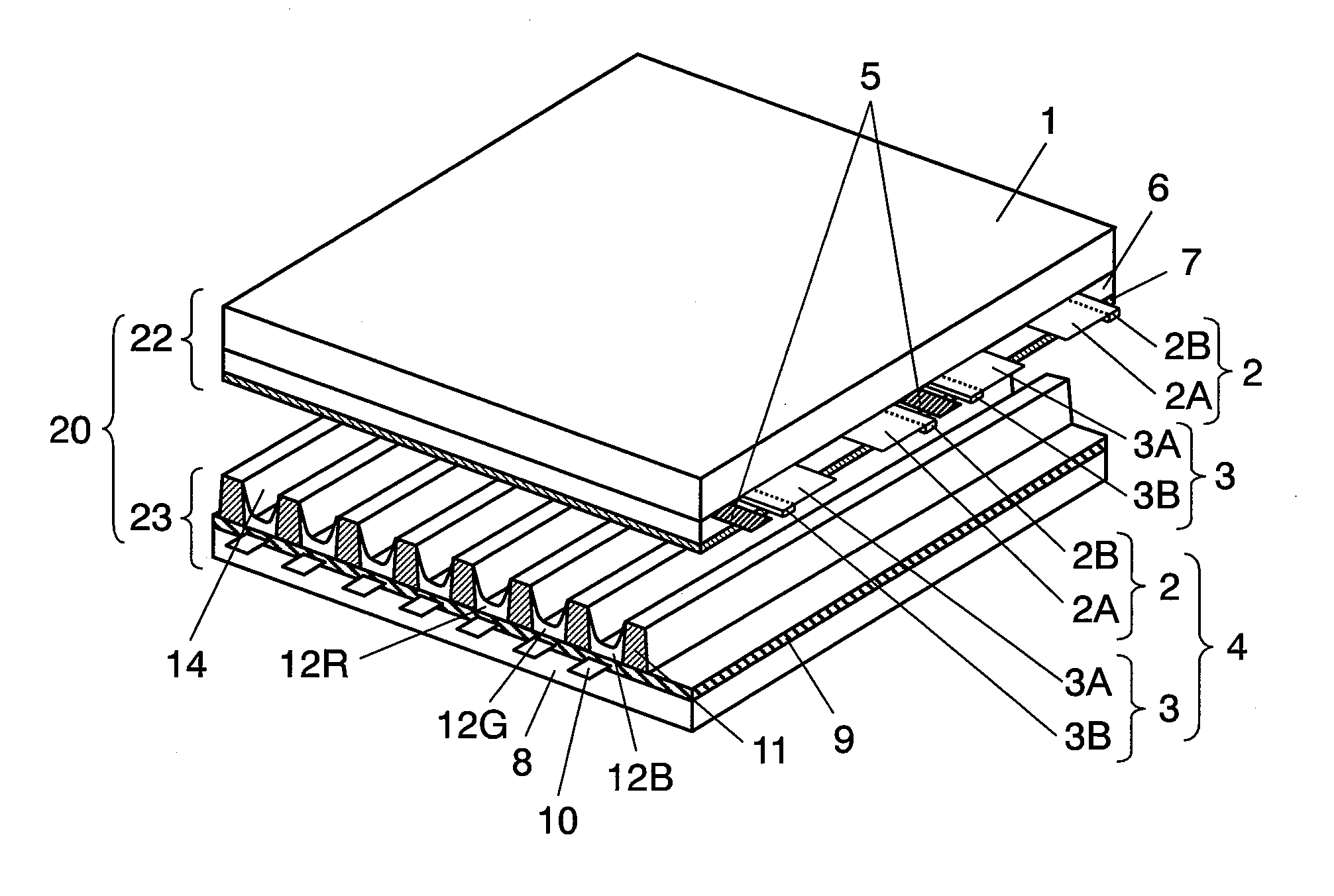
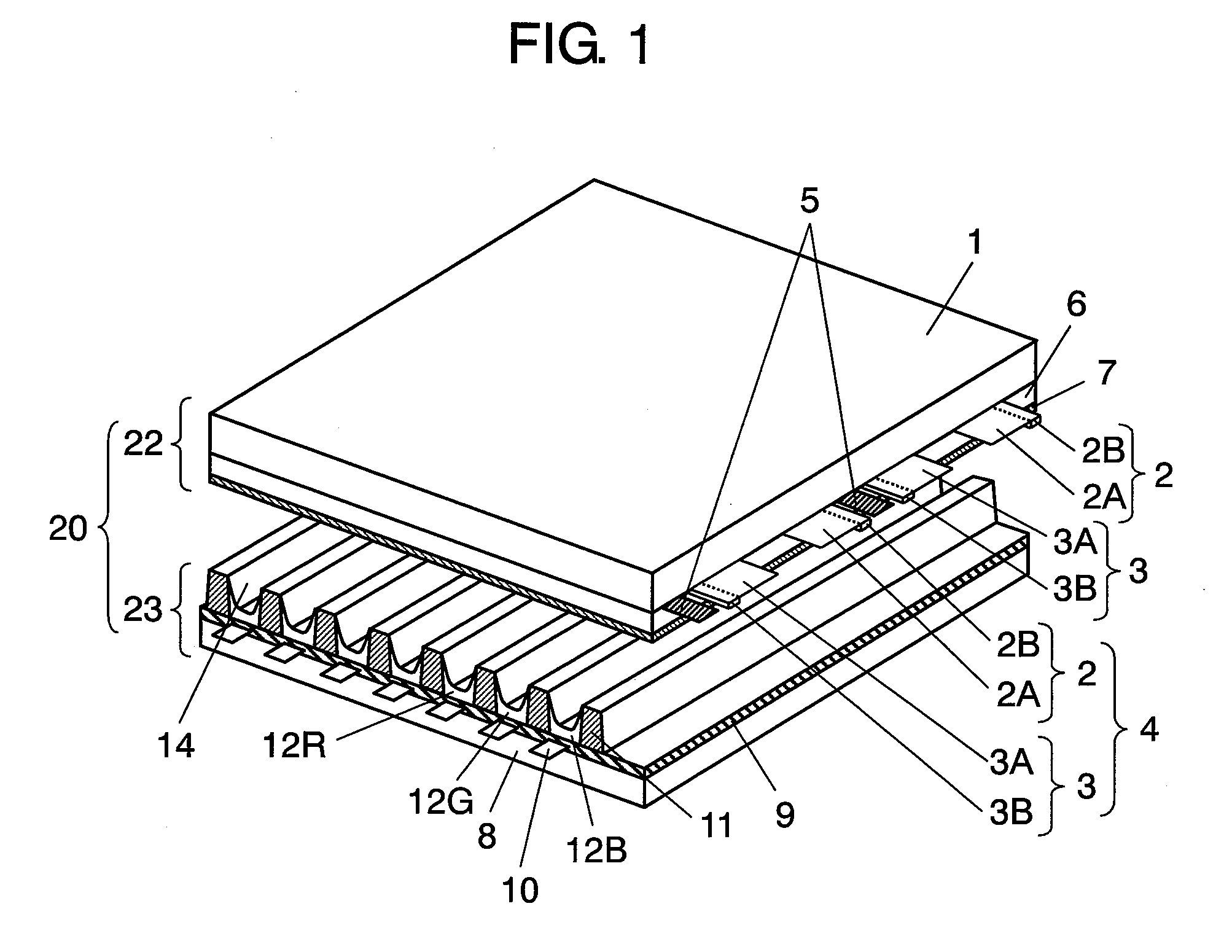
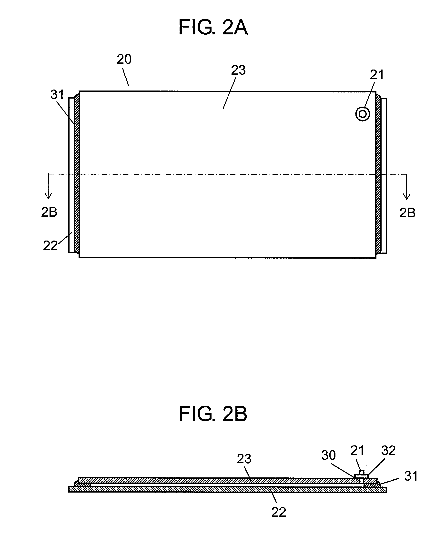
[0033]FIG. 1 is an exploded perspective view showing a partially enlarged plasma display panel (PDP) in an embodiment of the present invention, and FIGS. 2A and 2B are a plan view and a sectional view showing a state in which a front plate and a rear plate of the PDP shown in FIG. 1 are sealed and bonded.

[0034]PDP 20 includes front plate 22, rear plate 23, and evacuation pipe 21. Front plate 22 and rear plate 23 are arranged to face each other. Peripheries of front plate 22 and rear plate 23 are sealed and bonded, and discharge spaces 14 are formed by front plate 22, rear plate 23, and barrier ribs 11 formed on rear plate 23. Evacuation pipe 21 is used when discharge spaces 14 are evacuated to introduce the discharge gas into discharge spaces 14.

[0035]In front plate 22, pairs of scan electrode 2 for sequentially displaying and sustain electrode 3 for inputting a discharge sustaining signal are formed in a stripe shape on transparent front glass substrate 1. Display electrode 4 inclu...


PUM


Abstract

A plasma display panel is provided with a front substrate (22); a rear substrate (23) arranged to face the front substrate; and an exhaust tube (21). A discharge space is formed by sealing the circumference of the front substrate with the circumference of the rear substrate. The exhaust tube is connected to the rear substrate for exhausting the discharge space and filling the discharge space with a discharge gas. The exhaust tube is formed of a lead-free glass, and the ratio of its thickness to its outer diameter is 0.2 or more.

Description

[0001]This application is a U.S. National Phase application of PCT International Application PCT / JP2007 / 055534.TECHNICAL FIELD[0002]The present invention relates to a plasma display panel (hereinafter abbreviated as PDP) which is a flat plate type display apparatus used in a large-size television receiver or a public display and a production method thereof. Particularly, the present invention relates to an evacuation pipe which introduces a discharge gas while being provided in a PDP to evacuate discharge spaces, and a method of producing a PDP including the evacuation pipe.BACKGROUND ART[0003]A PDP can realize high definition and a large screen. Therefore, a 65-inch class television receiver, a large public display apparatus, and the like are being commercialized, and an over 100-inch product has also been realized.[0004]Basically, a PDP includes a front plate and a rear plate. The front plate includes a glass substrate, display electrodes, a dielectric layer, and a protective laye...

Claims


Application Information

Patent Timeline
Patent Type & Authority Applications(United States)
IPC IPC(8): H01J17/49H01J9/26H01J9/40H01J11/12H01J11/24H01J11/26H01J11/34H01J11/36H01J11/38H01J11/40H01J11/42H01J11/44H01J11/46H01J11/48H01J11/50H01J11/54
CPCH01J9/385H01J11/54H01J11/12H01J9/40H01J11/50
Inventor WADA, YASUMASANISHITANI, SEIJINISHINAKA, MASAKIYONEHARA, HIROYUKI
Owner PANASONIC CORP
Why Eureka
Try Eureka