Reconfigurable radiation densensitivity bracket systems and methods

a radiation densensitivity and bracket technology, applied in the field of wireless communication, can solve the problems of radiation pattern and radiation-susceptible circuitry issues, and counterpoise being susceptible to changes in the design and location of proximate circuitry, so as to reduce the effect of radiation-induced currents

Inactive Publication Date: 2010-05-27
KYOCERA CORP
View PDF102 Cites 1 Cited by
  • Summary
  • Abstract
  • Description
  • Claims
  • Application Information

AI Technical Summary

Benefits of technology

[0013]The present invention describes a reconfigurable radiation desensitivity bracket that can be added to the groundplane of a circuit proximate to a radiation source, to minimize the effects of radiation-induced currents. The bracket can be selectively tuned or switched in response to changes in frequency. Alternately considered, the bracket is space-reconfigurable to selectively redistribute current flow through the groundplane associated with radiated waves.

Problems solved by technology

Many conventional wireless telephones use a monopole or single-radiator design with an unbalanced signal feed.
However, the counterpoise is susceptible to changes in the design and location of proximate circuitry, and interaction with proximate objects when in use, i.e., a nearby wall or the manner in which the telephone is held.
As a result of the susceptibility of the counterpoise, the radiation patterns and communications efficiency can be detrimentally impacted.
Even if a balanced antenna is used, so that the groundplanes of proximate circuitry are not required as an antenna counterpoise, radiation pattern and radiation-susceptible circuitry issues remain.
This problem is compounded when an antenna, or a group of antennas operate in a plurality of frequency bands.
It is difficult, if not impossible, to design a wireless device to minimize the interaction between antenna radiation and susceptible circuitry in every one of its communication bands.
As a result, a conventional design must be optimized for one particular communication band, or the design must be compromised to have for some (minimal) effect in every communication band of interest.

Method used


Image

  • Reconfigurable radiation densensitivity bracket systems and methods
  • Reconfigurable radiation densensitivity bracket systems and methods
  • Reconfigurable radiation densensitivity bracket systems and methods

Examples


Embodiment Construction

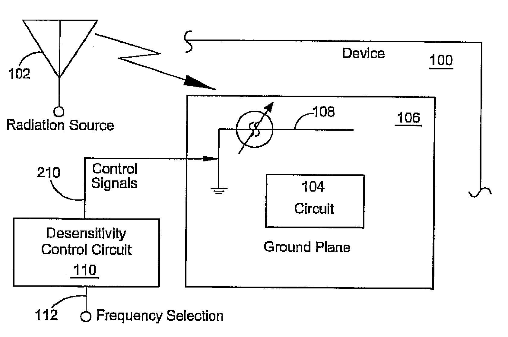
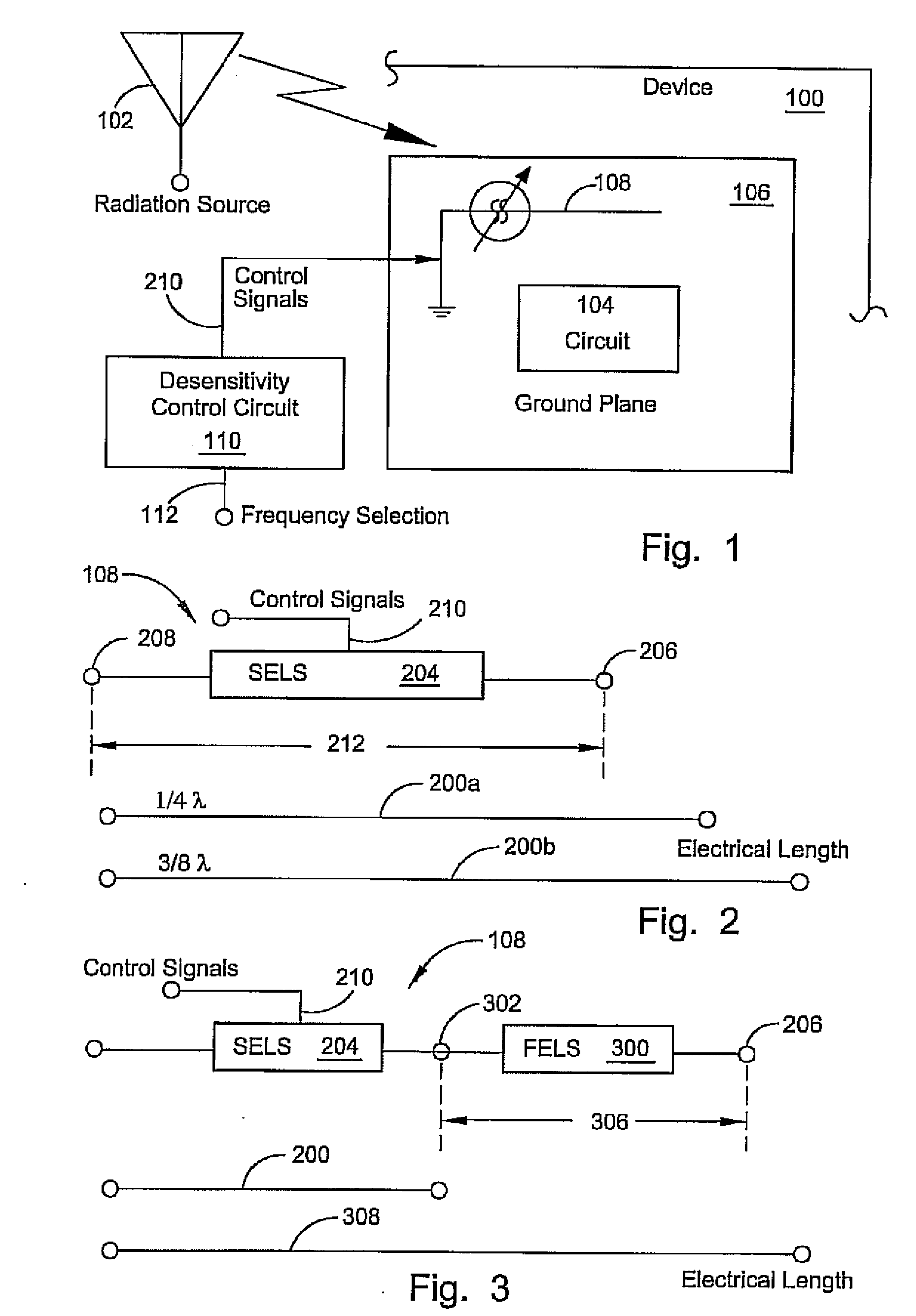
[0032]FIG. 1 is a schematic block diagram of the present invention device with a reconfigurable radiation desensitivity bracket. The device 100 comprises a radiation source 102 and an electrical circuit 104 having a groundplane 106. A reconfigurable radiation desensitivity bracket 108 is coupled to the groundplane 106. The electrical circuit 104 may be components, such as integrated circuits (ICs), resistors, transistors, and the like, mounted on a printed circuit board (PCB). Otherwise, the electrical circuit 104 may be a display, a connector, or keypad, to name a few examples. The radiation source 102 may be a transmitter, antenna, microprocessor, electrical component, camera, connector, signal cable, or IC, to name a few conventional sources.

[0033]Two primary uses of the present invention bracket are for use in a portable or base station wireless device, where circuitry is susceptible to radiating elements such as an antenna, transmitter, transmitter component such as a transisto...


PUM


Abstract

A method and device bracket are presented for reconfigurable radiation desensitivity. The method includes: accepting a radiated wave from a source such as a transmitter, antenna, microprocessor, electrical component, integrated circuit, camera, connector, or signal cable; in response to the radiated wave, creating a first current per units square (I / units2) through a groundplane of an electrical circuit such as a printed circuit board (PCB), display, connector, or keypad; accepting a control signal; and, in response to the control signal, creating a second I / units2 through the groundplane. This step couples the groundplane to a bracket having a selectable effective electrical length. Typically, the groundplane is coupled to a bracket with a fixed physical length section to provide a combined effective electrical length responsive to the fixed physical length and the selectable effective electrical length. The coupling mechanism can result from transistor coupling, p / n junction coupling, selectable capacitive coupling, or mechanically bridging.

Description

RELATED APPLICATIONS[0001]This application is a divisional application of U.S. application Ser. No. 10 / 940,206, filed Sep. 14, 2004, by Gregory Poilasne and Jordi Fabrega-Sanchez, which is hereby incorporated by reference. U.S. application Ser. No. 10 / 940,206 is a continuation-in-part application of U.S. application Ser. No. 10 / 775,722, filed Feb. 9, 2004, by Jordi Fabrega-Sanchez, Stanley S. Toncich and Allen Tran, which is hereby incorporated by reference. U.S. application Ser. No. 10 / 775,722 is a continuation-in-part application of U.S. application Ser. No. 10 / 120,603, filed Apr. 9, 2002, by Jordi Fabrega-Sanchez, Stanley S. Toncich and Allen Tran, which is hereby incorporated by reference, which claims the benefit of U.S. Provisional Application 60 / 283,093, filed Apr. 11, 2001, which is hereby incorporated by reference.[0002]In addition, this application relates to the following U.S. applications and patents, which are hereby incorporated by reference: “Reconfigurable Radiation ...

Claims


Application Information

Patent Timeline
Patent Type & Authority Applications(United States)
IPC IPC(8): H01Q1/52H01G7/06H01P1/203H01P1/213H01P5/04H01Q1/00H01Q1/24H01Q3/44H01Q9/04H01Q9/16H01Q9/28H01Q9/30H01Q13/02H01Q13/06H01Q13/20H03B5/18H03B5/36H03F1/56H03F3/191H03H7/01H03H7/12H03H7/20H03J5/24H03L1/02H03L7/18H04B1/30
CPCH01G7/06H01P1/203H01P1/20336H01P1/213H01P5/04H01Q1/00H01Q1/241H01Q1/243H01Q1/48H01Q1/52H01Q3/44H01Q9/0407H01Q9/0421H01Q9/0442H01Q9/16H01Q9/28H01Q9/30H01Q13/02H01Q13/06H01Q13/203H03B5/1841H03B5/362H03F1/56H03F3/191H03H7/20H03J5/246H03L1/022H03L7/18H04B1/30
Inventor POILASNE, GREGORYFABREGA-SANCHEZ, JORGE
Owner KYOCERA CORP
Why Eureka
Try Eureka